
Method of manufacturing a device

a manufacturing method and technology of a device, applied in the direction of magnetic bodies, instruments, printed element electric connection formation, etc., can solve the problems of material waste, inability to realize conditions, and complex surface preparation

Inactive Publication Date: 2006-11-07
SEIKO EPSON CORP
View PDF11 Cites 24 Cited by
  • Summary
  • Abstract
  • Description
  • Claims
  • Application Information

AI Technical Summary

Problems solved by technology

Such a photolithographic method uses the etching processing to repeatedly remove many portions of the film, and so involves a disadvantage that a material for formation of a film is wasted.
However, the method of forming a wiring pattern with the use of the ink jet system involves the following problems.
More specifically, since a repellent property is required of a substrate, on which a conductive liquid is discharged, in forming a fine wiring pattern having a large film thickness, it is necessary to subject a surface of a substrate to surface preparation for ensuring a repellent property as a pretreatment, and so such surface preparation makes a manufacturing process complex.
Also, some substrate materials cannot realize conditions of surface preparation for imparting a repellent property of a certain level, that is, some substrate materials make conditions of surface preparation very difficult.
Further, while it has been proposed to use the ink jet system to form an interlayer insulating film in the case of forming multilayer wirings, a manufacturing process is made complex because it is necessary to form a wiring pattern by carrying out the surface preparation every time an interlayer insulating film is formed.
For example, a substrate made of plastics does not posses resistance to the heat treatment, so that it cannot be employed in a method of forming a wiring pattern with the ink jet system.

Method used


Image

  • Method of manufacturing a device
  • Method of manufacturing a device
  • Method of manufacturing a device

Examples


Embodiment Construction

[0040]An explanation will be given below to a method of manufacturing a device, according to the invention, and embodiments of a device, a non-contact type card medium, and an electronic equipment with reference to the drawings.

[0041]In addition, a droplet discharge method referred to in the invention is one, in which liquid droplets are discharged into a desired region to form a desired pattern including a substance being discharged, and the method is in some cases called an ink jet method. In this case, however, discharged liquid droplets do not correspond to so-called ink used in printing but comprise a liquid body containing a material constituting a device, the material containing, for example, a conductive substance constituting a device, or a substance capable of functioning as an insulating substance. Further, droplet discharging is not limited to atomizing at the time of discharging but includes the case where droplets of a liquid body are continuously (successively) discha...


PUM

PropertyMeasurementUnit
temperatureaaaaaaaaaa
insulatingaaaaaaaaaa
conductionaaaaaaaaaa

Abstract

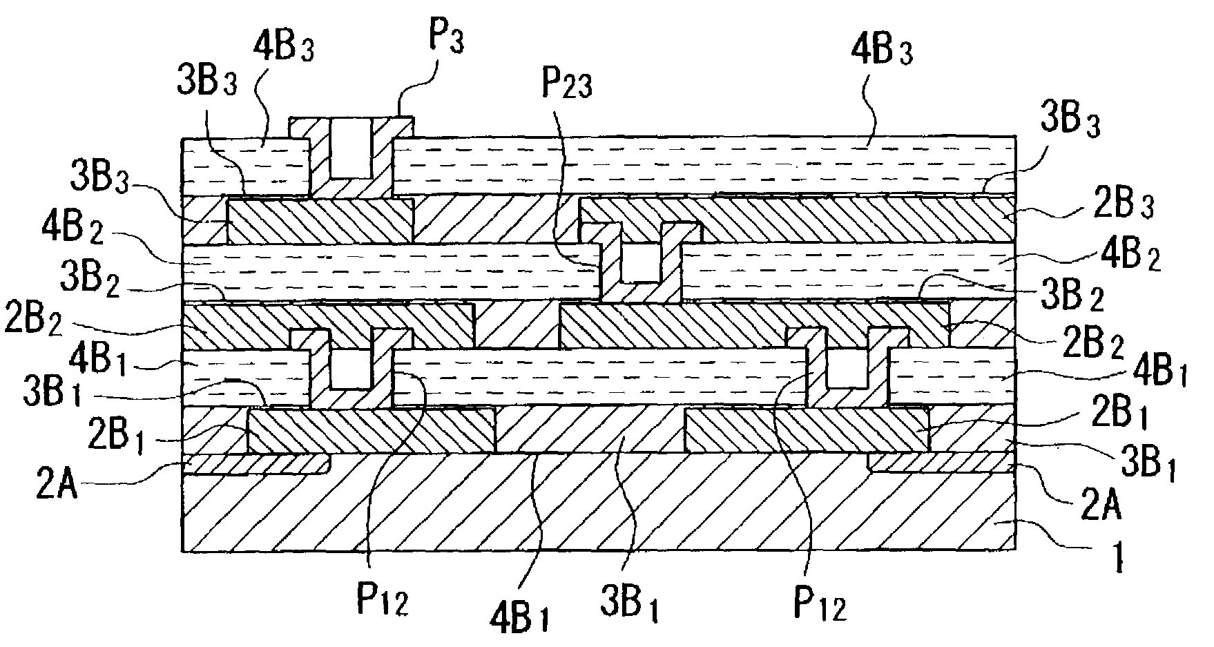
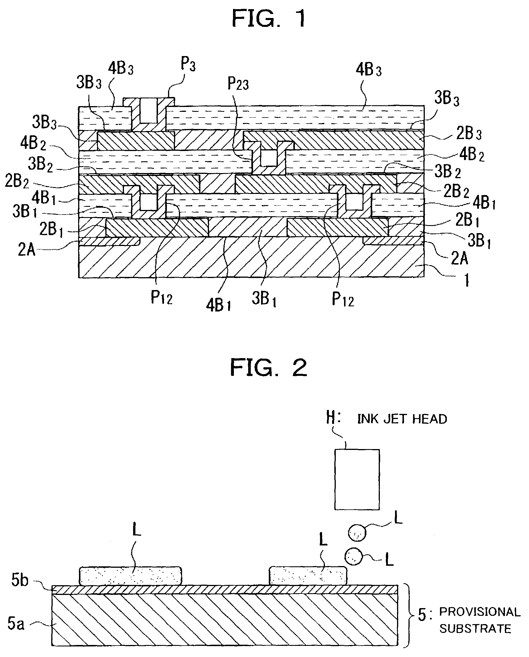
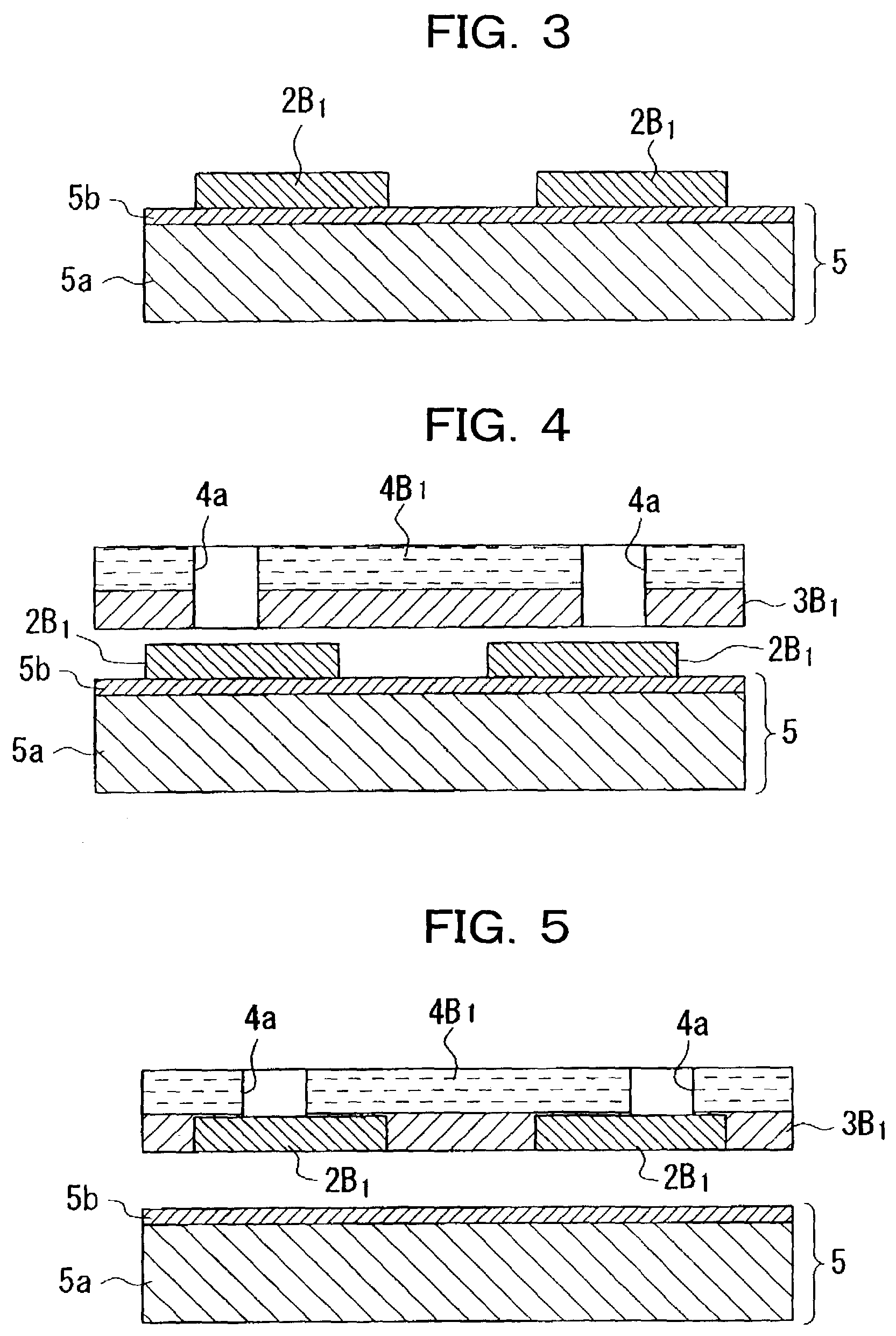
Wirings 2B1 are formed by application of heat treatment after an ink jet system is used to discharge a conductive liquid L onto a provisional substrate 5 having a predetermined repellent property, bonding an insulating layer 4B1 to the wirings 2B1 with an adhesive material 3B1 therebetween, peeling and removing the provisional substrate 5, and bonding and fixing the wirings 2B1 together with the insulating film 4B1 to a main substrate 1 by an adhesive material 3B1.

Description

BACKGROUND OF THE INVENTION[0001]1. Technical Filed[0002]The present invention relates to a method of manufacturing a device, a device, a non-contact type card medium, and electronic equipment.[0003]2. Related Art[0004]As well known, the photolithographic method is generally used to form printed-circuit boards incorporated into various electronic equipment and wiring patterns in various semiconductor devices. The photolithographic method comprises using an etching processing to repeatedly leave only necessary portions on a film formed on a substrate and remove remaining portions to form various circuit elements and wiring patterns on the substrate. Such a photolithographic method uses the etching processing to repeatedly remove many portions of the film, and so involves a disadvantage that a material for formation of a film is wasted. As a method of overcoming such disadvantage, there has been proposed a method of directly forming a wiring pattern in a painting manner by the use of ...

Claims


Application Information

Patent Timeline
Patent Type & Authority Patents(United States)
IPC IPC(8): H05K3/30B42D15/10B41J2/01G06K19/07G06K19/077H05K3/20H05K3/38H05K3/40H05K3/46
CPCH05K3/207H05K3/4069H05K3/4614H05K1/0306Y10T29/49147H05K3/1275H05K3/386H05K2201/0195H05K2201/0352H05K2201/09509H05K2201/09981H05K2203/013H05K2203/0534H05K2203/061H05K2203/063H05K2203/1173Y10T29/49169Y10T29/49002Y10T29/4913Y10T29/49128Y10T29/49162Y10T29/49155Y10T29/49073Y10T29/49224H05K3/125
Inventor HASHIMOTO, TAKASHI
Owner SEIKO EPSON CORP
Learn More