Electrical plug, holder, system having an electrical plug and a holder, and method of making a connection between an electrical plug and a holder

a technology of electrical plugs and holder plates, applied in the field of electric plugs, can solve the problems of achieving the smallest transition resistance, and achieve the effect of achieving the smallest possible transition resistance, done quickly and without tools

Inactive Publication Date: 2006-11-07
NEWFREY
View PDF18 Cites 21 Cited by
  • Summary
  • Abstract
  • Description
  • Claims
  • Application Information

AI Technical Summary

Benefits of technology

[0004]The object of the invention is to create an electrical connection between a flexible electric conductor and a rigid holder by means of a plug, the plug being first connected to the electric conductor and then to the rigid holder. Such a connection is required for example for the junction of a ground cable to a ground holder of the chassis of a motor vehicle. The object consisted further in that mounting of the plug provided with the electric conductor on the holder might be done quickly and without tools, and in that a securely realizable snap-click assembly would be possible. Further, the smallest possible transition resistances are to be achieved.
[0008]By the measures set forth in the dependent claims, advantageous refinements and improvements of the electrical plug specified in the independent claims, of the system consisting of electrical plug and holder, and of the method of making a connection between an electrical plug and a holder, are made possible. It is especially advantageous to configure the contact leg with a crook directed towards the clamp edge of the clamp opening and arranged at the clamp location. Owing to the small areas of contact of the contact leg at the clamp location, this provides a secure connection between the electric conductor and the holder.
[0009]It is advantageous, further, to bend the end of the flat spring material opposed to the clamp location towards the holder in such manner that after the plug has been mounted on the holder, it will catch in or engage a recess in the holder. In this way, the security of the connection is improved as well, since when the holder has been thrust all the way into the plug, the engagement of the bent end of the flat spring material in the recess of the holder takes place. Therefore, it is not possible for the holder to pull out of the plug without anything more. It is likewise of advantage to provide the flat spring material with an opening for release of the plug, where upon insertion of an auxiliary means, for example a pin, through this opening, the end of the flat spring material opposed to the clamping location is bent up, so that the bent-over end of the flat spring material no longer engages the recess of the holder, and the plug can be drawn off from the holder. It is advantageous further to provide the end located opposed to the clamp location with wing elements serving to position the holder in relation to the clamp spring. The electrical plug further comprises advantageous wing elements arranged on the flat spring material and fixing the clamp spring in a recess of the housing.
[0010]To seal the housing from environmental influences, it is advantageous to provide the openings through which the electric conductor and / or the holder are inserted with sealing lips. For the holder, it is advantageous if, for use of the plug to produce a contact between ground cable and chassis of a motor vehicle, the holder is welded onto the chassis.

Problems solved by technology

Further, the smallest possible transition resistances are to be achieved.

Method used


Image

  • Electrical plug, holder, system having an electrical plug and a holder, and method of making a connection between an electrical plug and a holder
  • Electrical plug, holder, system having an electrical plug and a holder, and method of making a connection between an electrical plug and a holder
  • Electrical plug, holder, system having an electrical plug and a holder, and method of making a connection between an electrical plug and a holder

Examples


Embodiment Construction

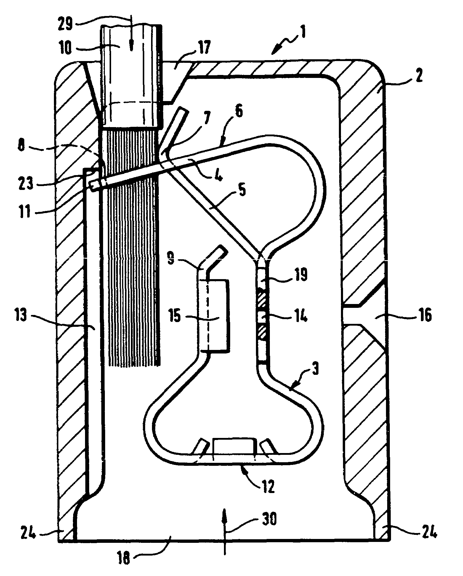
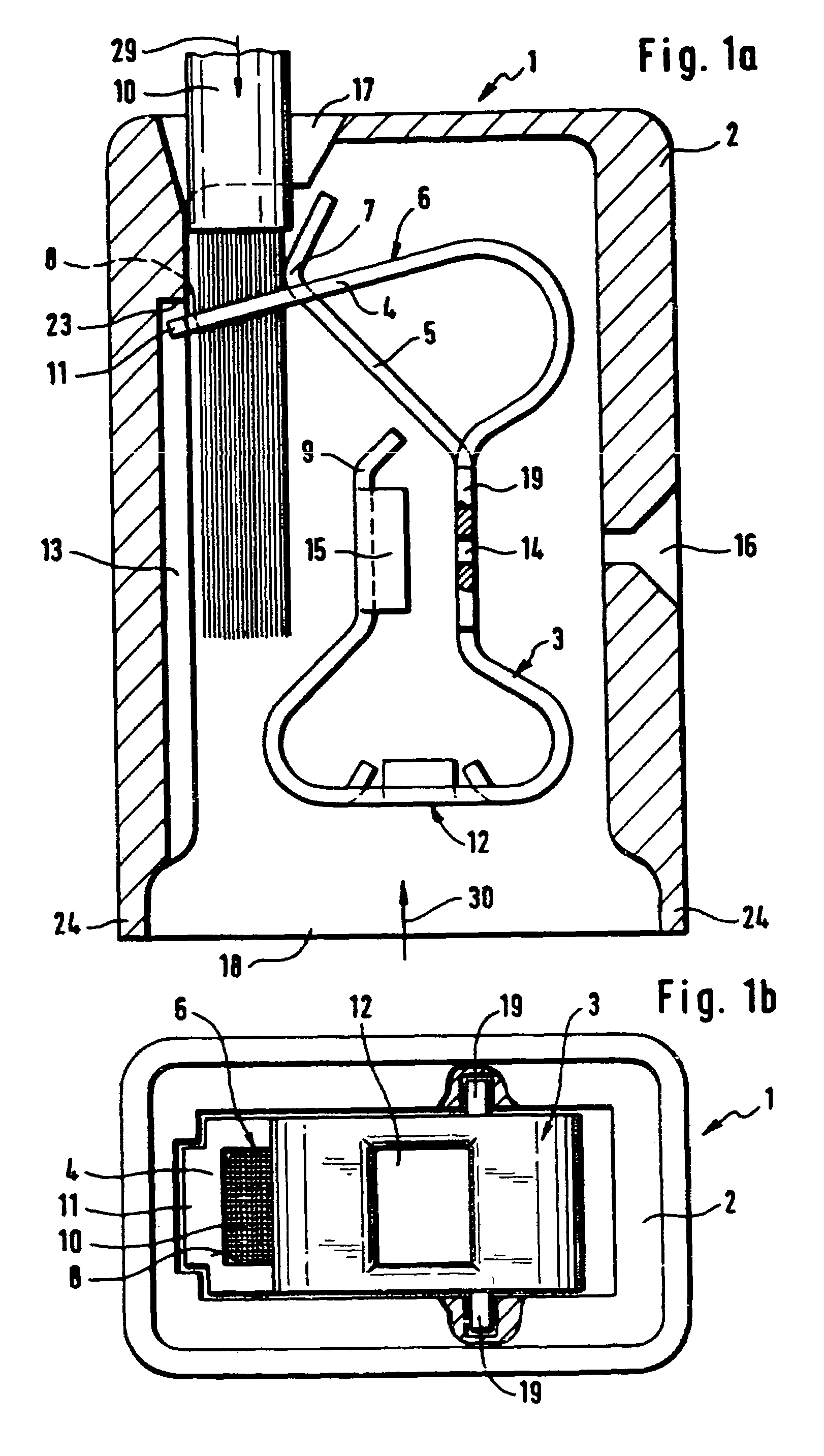
[0017]FIG. 1a shows a longitudinal section of a plug 1 according to the invention. The plug 1 comprises a housing 2 in which a clamp spring 3 made of a flat spring material is arranged. The clamp spring 3 forms a spring clamp connection for connecting a flexible electric conductor 10 to the end piece of a rigid holder not shown in this figure.

[0018]The clamp spring 3 comprises a clamp leg 4 and a contact leg 5, the contact leg 5 being stamped out of the flat spring material in the shape of a tongue and so bent away that the contact leg 5 extends through the clamp opening 6 of the clamp leg 4 formed by the punched-out tongue. The clamp leg 4 is bent over to the rear and bent closed again in the form of a loop onto the contact leg 5. The edge 8 of the clamp opening located opposed to the bent edge of the contact leg 5 is also referred to as a clamp edge, since this edge together with the crooked portion 7 of the contact leg 5 forms the clamp location.

[0019]The electrical plug 1 pictur...


PUM


Abstract

An electrical plug includes a housing and a spring clamp to connect a flexible electric conductor to an end piece of a rigid holder. The clamp spring includes a contact leg and a clamp leg. The clamp leg is bent closed in a loop onto the contact leg end providing a clamp opening through which the contact leg end protrudes. The clamp leg and a clamp opening edge positioned opposite to the clamp leg form a clamp location in which the electric conductor passed through the clamp opening is clamped before mounting the plug on the holder. After mounting, the holder extends through the clamp opening displacing the contact leg from the electric conductor. The holder and clamp spring clamp the electric conductor and form an electrical connection between the holder and electric conductor.

Description

CROSS-REFERENCE TO RELATED APPLICATIONS[0001]This application claims the benefit of German Patent Application No. 10353356.7, filed Nov. 14, 2003. The disclosure of the above application is incorporated herein by reference.FIELD OF THE INVENTION[0002]The invention relates to an electrical plug having a housing and a spring clamp connection for connecting a flexible electric conductor to the end piece of a rigid holder. The invention relates further to such a holder, to a suitable system consisting of an electrical plug and a holder, and to a method of making a connection between an electrical plug and a holder.BACKGROUND OF THE INVENTION[0003]There are known connecting clamps having a housing and a spring clamp connection for connecting a flexible electric conductor to current rails, where the spring clamp connection consists of a clamp spring made of flat spring material. The connecting clamps disclosed for example in printed sources DE 3,514,099 C2, DE 198 02 945 A1 or DE 198 17 9...

Claims


Application Information

Patent Timeline
Patent Type & Authority Patents(United States)
IPC IPC(8): H01R11/20H01R4/26H01R4/48H01R4/64H01R43/00
CPCH01R4/4845H01R4/48455
Inventor MUELLER, MANFRED
Owner NEWFREY
Why Eureka
Try Eureka