Projector type vehicular lamp device

a technology of projectors and lamps, applied in semiconductor devices, light sources, fixed installations, etc., can solve the problems of difficult to become a design value, difficult to meet the requirements of optical axial direction requiring high accuracy, and increase the weight of lamp devices

Inactive Publication Date: 2006-11-14
ICHIKOH IND LTD
View PDF12 Cites 20 Cited by
  • Summary
  • Abstract
  • Description
  • Claims
  • Application Information

AI Technical Summary

Benefits of technology

[0013]Accordingly, an object of the present invention is to provide a projector type vehicular lamp device which can intend to reduce a weight of the lamp device and a number of parts, can stably obtain an excellent light distributing performance, and can obtain a sufficient illumination intensity of a hot zone of a light distributing pattern by achieving a reflecting performance of a concave mirror to the maximum.
[0015]In accordance with the structure mentioned above, the light of the LED of the small projector type lamp device for forming a cutoff line and for not forming the cutoff line is emitted toward the small concave mirror in each of the small projector type lamp devices, is reflected by the small concave mirror so as to reach the small convex lens, and passes through the small convex lens, thereby being modulated to the parallel light flux so as to be emitted to the front side of the vehicular lamp device, so that it is possible to form a desired light distributing pattern as a whole.

Problems solved by technology

However, in the conventional vehicular lamp device 100, since the outgoing light of the light source bulb 2 has a high heat energy, it is impossible to achieve a sufficient heat radiation only by the through holes 1b and 1c, and it is necessary to form the convex lens 3 by a glass, whereby there is a problem that an increase of weight in the lamp device is caused.
As mentioned above, since the materials used in each of the parts are different in the vehicular lamp device 100, it is necessary to form each of the parts independently and assemble a plurality of parts, however, there is a problem that a dimension in an optical axial direction requiring a high accuracy is hard to become a design value due to a dispersion of assembly and a dispersion of part dimension, and a dispersion of light distributing performance is enlarged.
Further, the number of the parts in the vehicular lamp device 100 is large, whereby a parts management is complicated and an assembling man-hour is increased, so that there is a problem that a cost increase is caused by extension.
Since the vehicular lamp device 100 is provided with the through holes 1b and 1c, a reflecting performance near a center portion of the concave mirror 1 is lowered, and there is also a problem that an illumination intensity of a hot zone in the center portion of the light distributing pattern is lowered by extension.

Method used


Image

  • Projector type vehicular lamp device
  • Projector type vehicular lamp device
  • Projector type vehicular lamp device

Examples


Embodiment Construction

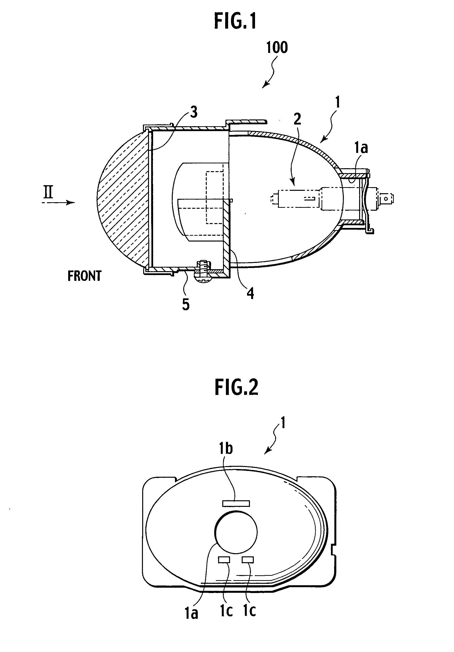
[0032]A description will be given below of the present invention on the basis of embodiments thereof. In this case, a description will be given of constituting elements having the same functions as those disclosed in FIGS. 1 and 2 by attaching the same reference numerals.

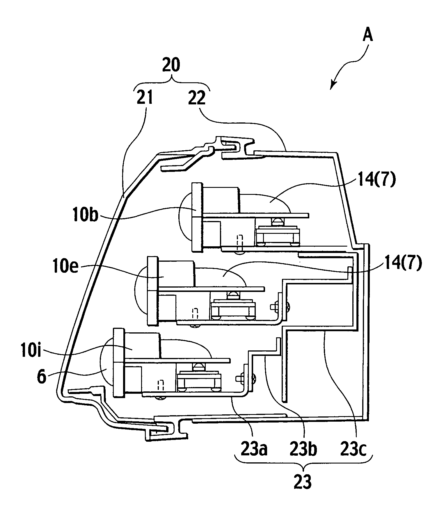
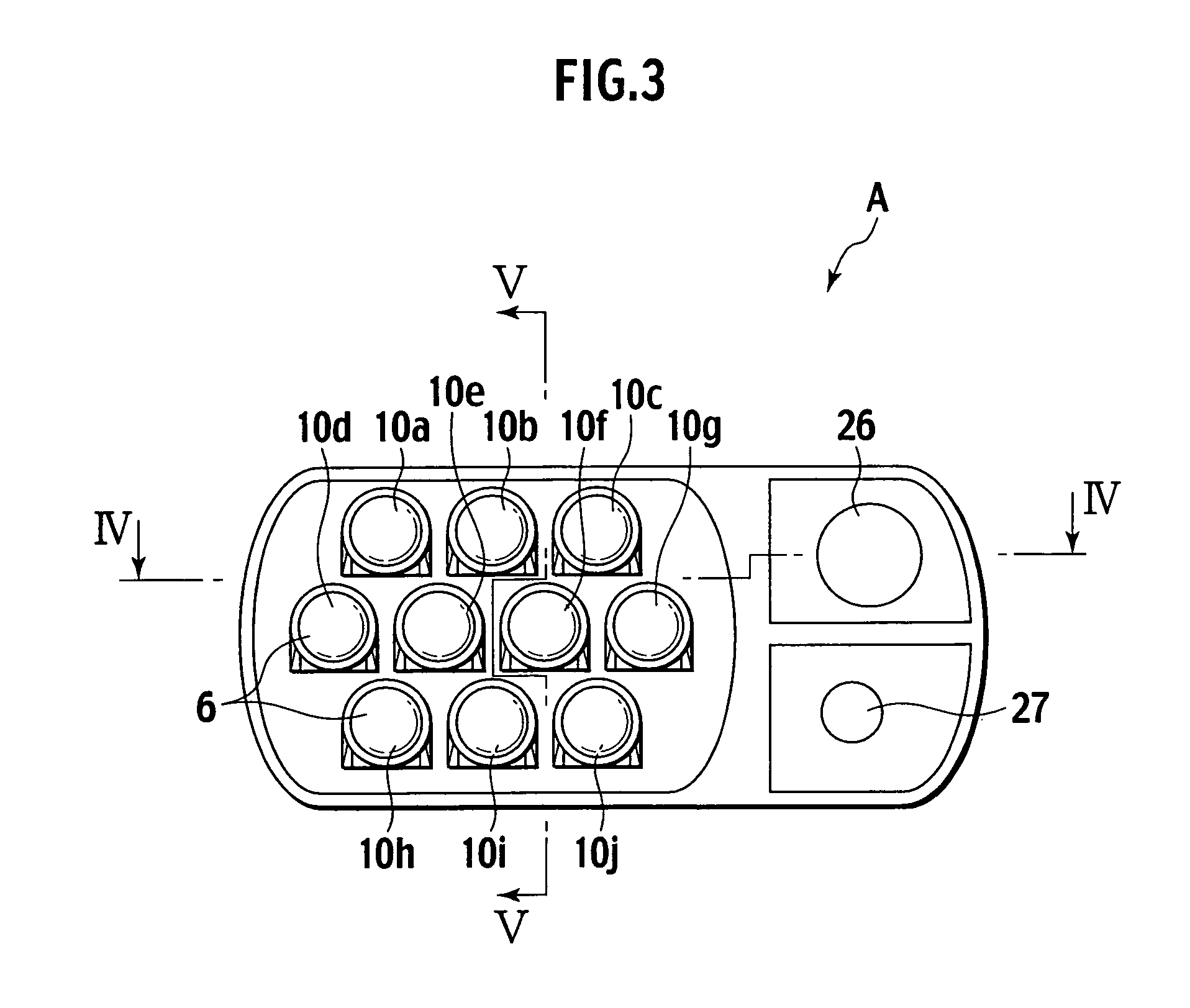
[0033]FIGS. 3 to 5 show a projector type vehicular lamp device A of the present invention. The vehicular lamp device A including a plurality of small projector type lamp devices 10a, 10b, 10c, 10d, 10e, 10f, 10g, 10h, 10i and 10j each having an LED 11 (refer to FIG. 6) built-in as a light source into a housing 20 (refer to FIG. 4).

[0034]As shown in FIG. 4, the housing 20 includes a casing 22 in which a front portion is open (an opening of the casing 22), and a plain glass 21 covering the opening of the casing 22. Further, a plurality of the small projector type lamp devices 10a to 10j are incorporated into the housing 20 by being firmly fixed to the casing 22 via a mounting device 23. Further, the mounting device 23...


PUM


Abstract

Small projector type lamp devices for forming a cutoff line and for not forming the cutoff line having LED as a light source are formed by using small reflectors and small convex lenses made of resin. A shade having an approximately horizontal reflection surface extended to a rear side from a front end of a bent edge portion and a front end step portion formed in a front end of the reflection surface are formed in the small reflector of the lamp device, and a shade having the reflection surface is formed in the small reflector of the lamp device. A plurality of lamp devices are incorporated into a housing so as to structure a vehicular lamp device.

Description

BACKGROUND OF THE INVENTION[0001]1. Field of the Invention[0002]The present invention relates to a projector type vehicular lamp device applied as a head lamp and using a light emitting diode (LED) in a light source.[0003]2. Description of the Related Art[0004]FIG. 1 shows a conventional projector type vehicular lamp device 100 (for example, refer to a microfilm of Japanese Utility Model Application No. 4-76322 (Japanese Utility Model Application Laid-Open Publication No. 6-41010). The vehicular lamp device 100 comprises a light source bulb 2 provided near a first focus of a concave mirror 1, and a convex lens 3 modulating a light flux outgoing from the light source bulb 2 and reflected on the concave mirror 1 to an approximately parallel light flux so as to emit to a front side of the vehicular lamp device 100 (a left side in FIG. 1).[0005]In detail, the vehicular lamp device 100 is structured such that a shade 4 is provided between the light source bulb 2 and the convex lens 3, an...

Claims


Application Information

Patent Timeline
Patent Type & Authority Patents(United States)
IPC IPC(8): F21V7/00F21S8/10F21V11/16F21V14/02F21V17/00F21V19/00F21W101/10F21Y101/00
CPCF21S48/1159F21S48/1388F21S48/145F21S48/1104F21S48/155F21Y2101/02F21Y2115/10F21S41/19F21S41/43F21S41/55F21S41/365F21S41/148F21S41/153
Inventor IWASAKI, KAZUNORI
Owner ICHIKOH IND LTD
Why Eureka
Try Eureka