Supercharge Your Innovation With Domain-Expert AI Agents!

Flat cable and connector as well as electronic device

a technology of flat cables and electronic devices, applied in the field of flat cables, can solve the problems of cumbersome operation of fitting flat cables to connectors, incomplete flat cable insertion, etc., and achieve the effect of high degree of integration of flat cables, connectors and electronic devices

Inactive Publication Date: 2006-11-14
SONY CORP +1
View PDF13 Cites 31 Cited by
  • Summary
  • Abstract
  • Description
  • Claims
  • Application Information

AI Technical Summary

Benefits of technology

The present invention provides a flat cable and connector that can reliably electrically connect to each other when inserted into the connector. The flat cable has wires formed in a flexible base member, which is designed to be engaged with corresponding projections in the connector to take a right position in the connector. This ensures accurate alignment between the flat cable and the connector, and allows for a high degree of integration of flat cables, connectors, and electronic devices. The invention also provides a connector with a movable pressurizing member to securely position the flat cable in the connector. Overall, the invention improves the reliability and efficiency of connecting electronic devices with external connectors.

Problems solved by technology

The use of a jig makes the operation of fitting a flat cable to a connector a cumbersome one.
Additionally, there arise problems including that the flat cable is inserted incompletely into the connector and / or fitted to the latter aslant more often than not.

Method used


Image

  • Flat cable and connector as well as electronic device
  • Flat cable and connector as well as electronic device
  • Flat cable and connector as well as electronic device

Examples


first embodiment

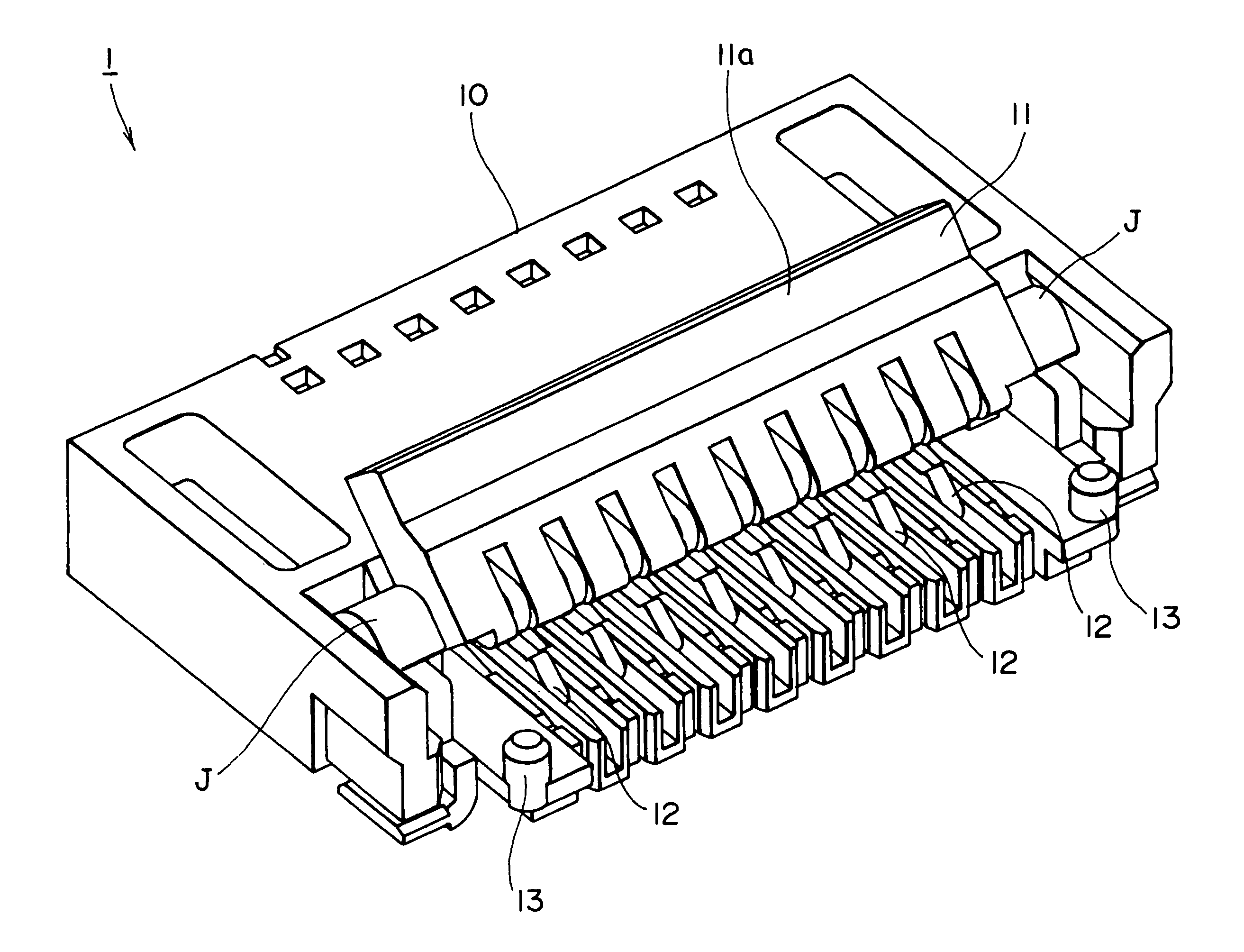
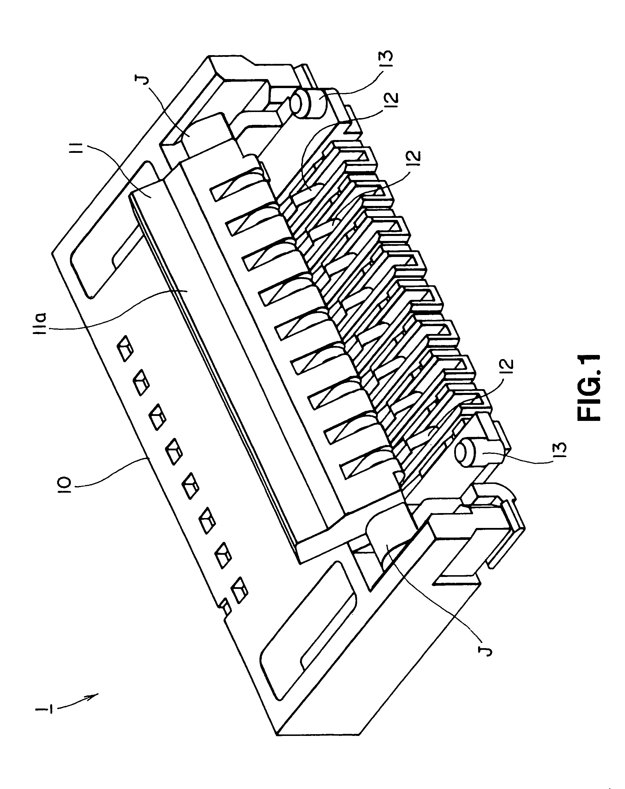
[0039]FIG. 1 is a schematic perspective view of connector according to the invention. Referring to FIG. 1, the connector 1 comprises a main body 10 adapted to receive a flat cable, which will be described in greater detail hereinafter and is to be inserted into it, and a movable pressurizing member 11 adapted to press and rigidly hold the flat cable in a state where the flat cable is inserted into the main body 10.

[0040]The main body 10 is provided at the position for receiving the flat cable with contacts 12 to be used for establishing electric connection with the flat cable. A plurality of contacts 12 are arranged so as to be insulated from each other and each of the contacts 12 has a bent and upwardly projecting profile so as to make itself resilient and operate like a spring. With this arrangement, when the flat cable is inserted into the main body 10, the wires of the flat cable reliably contact the corresponding respective contacts 12 of the connector 1 due to the resiliency o...

second embodiment

[0049]The main body 10 of the connector 1 of the second embodiment is also provided at the position for receiving the flat cable with contacts 12 to be used for establishing electric connection with the flat cable. A plurality of contacts 12 are arranged so as to be insulated from each other and each of the contacts 12 has a bent and upwardly projecting profile so as to make itself resilient and operate like a spring. With this arrangement, when the flat cable is inserted into the main body 10, the wires of the flat cable reliably contact the corresponding respective contacts 12 of the connector 1 due to the resiliency of the contacts 12.

[0050]The pressurizing member 11 has a keep plate 11a, which is opened and closed as the pressurizing member 11 is turned around an axis J. The flat cable is pinched in the main body 10 as the keep plate 11a of the pressurizing member 11 is closed so that the flat cable is reliably prevented from being pulled out.

[0051]The single projection 13 arran...

third embodiment

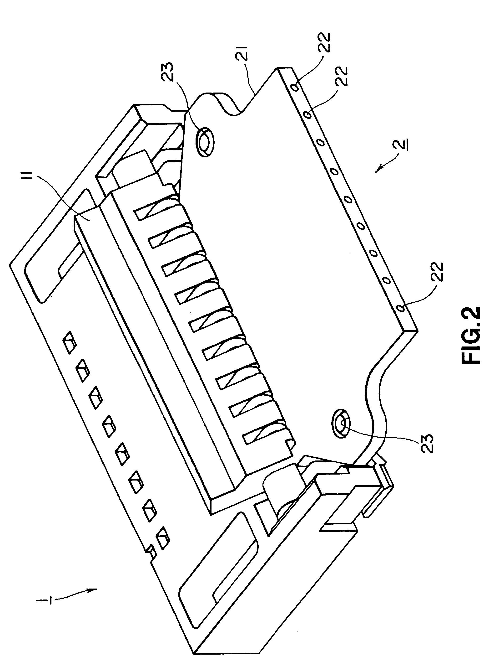
[0058]The main body 10 of the connector 1 of the third embodiment is also provided at the position for receiving the flat cable with contacts 12 to be used for establishing electric connection with the wires 22 of the flat cable 2. A plurality of contacts 12 are arranged so as to be insulated from each other and each of the contacts 12 has a bent and upwardly projecting profile so as to make itself resilient and operate like a spring. With this arrangement, when the flat cable 2 is inserted into the main body 10, the wires 22 of the flat cable 2 reliably contact the corresponding respective contacts 12 of the connector 1 due to the resiliency of the contacts 12.

[0059]The pressurizing member 11 has a keep plate 11a, which is opened and closed as the pressurizing member 11 is turned around an axis J. The flat cable is pinched in the main body 10 as the keep plate 11a of the pressurizing member 11 is closed so that the flat cable is reliably prevented from being pulled out.

[0060]The pr...


PUM

PropertyMeasurementUnit
flexibleaaaaaaaaaa
resilientaaaaaaaaaa
resiliencyaaaaaaaaaa

Abstract

A connector 1 according to the invention comprises a main body 10 for receiving the front end of a flat cable 2 being inserted therein, a movable pressurizing member 11 adapted to press and rigidly secure in position the flat cable 2 inserted into the main body 10 and projections 13 arranged either on the main body 10 or on the pressurizing member 11 so as to be engaged respectively with the corresponding holes 23 of the flat cable 2 when the front end of the flat cable is inserted into the connector 1 to take a right position in the connector 1. The flat cable 2 comprises a flexible base member 21 and wires 22 formed in the flexible base member 21, the flexible base member 21 being provided with holes 23 to be engaged respectively with the corresponding projections 13 arranged in the connector 1 when the flexible base member 21 is inserted into the connector 1 to take a right position in the connector 1.

Description

BACKGROUND OF THE INVENTION[0001]1. Field of the Invention[0002]This invention relates to a flat cable formed by arranging wires in a flexible base member and also to a connector for receiving and rigidly securing such a flat cable as well as to an electronic device using such a connector for electric connection.[0003]The present application claims priority from Japanese Patent Application No. P2003-327498 filed on Sep. 19, 2003, and No. P2003-386173 filed on Nov. 17, 2003, the content of which is hereby incorporated by reference into this application.[0004]2. Related Background Art[0005]Many flat cables have been and being used for electrically connecting circuit boards. Such a flat cable is formed by arranging a plurality of wires in parallel with each other in a flexible base member of an electrically insulating material and adapted to be effectively used for wiring and electrically connecting circuit boards with or without movable parts interposed between them.[0006]Generally, a...

Claims


Application Information

Patent Timeline
Patent Type & Authority Patents(United States)
IPC IPC(8): H01R13/15H01B7/08H01R12/77H01R12/78H01R12/79H01R12/88H05K1/11H05K7/12
CPCH01R12/88H01R12/772H01R12/79
Inventor KAYAMA, SHUNSHIMIZU, YUKIKOIIDA, MASAYOSHIYAMAGUCHI, TOMISABUROKUNISHI, SHINSUKEASO, AKIRA
Owner SONY CORP
Features
  • R&D
  • Intellectual Property
  • Life Sciences
  • Materials
  • Tech Scout
  • Unparalleled Data Quality
  • Higher Quality Content
  • 60% Fewer Hallucinations
Learn More