
Single-port to multi-port cable assembly

a multi-port, single-port technology, applied in the direction of fixed connections, electrical discharge lamps, coupling device connections, etc., can solve the problems of limited storage capacity, limited cable length, parallel scsi buses reaching performance limits,

Inactive Publication Date: 2006-11-14
HON HAI PRECISION IND CO LTD
View PDF7 Cites 53 Cited by
  • Summary
  • Abstract
  • Description
  • Claims
  • Application Information

AI Technical Summary

Benefits of technology

[0008]A primary object, therefore, of the present invention is to provide a high-speed cable assembly for transmitting signals between a first electrical device and at least two second electrical devices.

Problems solved by technology

As disk interconnect speeds continue to rise, existing parallel ATA and parallel SCSI buses are reaching their performance limits because that parallel transmissions are susceptible to crosstalk across multiple streams of wide ribbon cable that adds line noise and can cause signal errors—a pitfall that has been remedied by slowing the signal, limiting cable length or both.
As widely known, a storage device of the personal computer or the server has only a limited storage capability, which is hard to meet users' higher and higher requirements.
However, using large numbers of cable assemblies must increase complexity and occupy larger space in the electrical device.
However, the similar problem is existed.

Method used


Image

  • Single-port to multi-port cable assembly
  • Single-port to multi-port cable assembly
  • Single-port to multi-port cable assembly

Examples


Embodiment Construction

[0020]Reference will now be made in detail to preferred embodiments of the present invention.

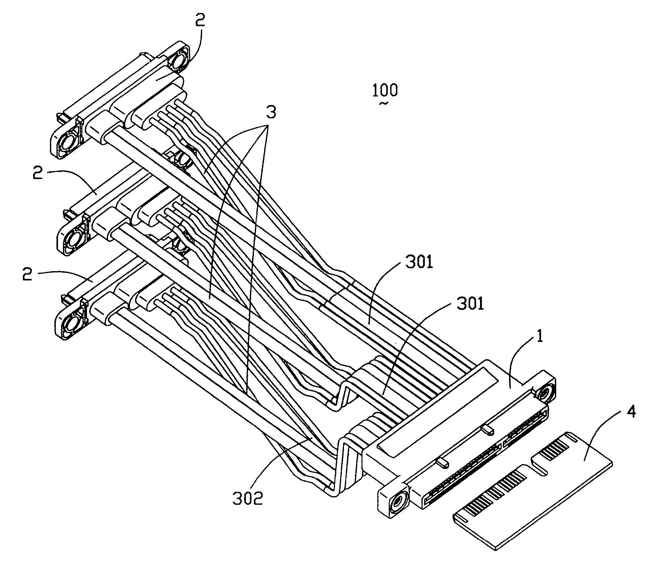
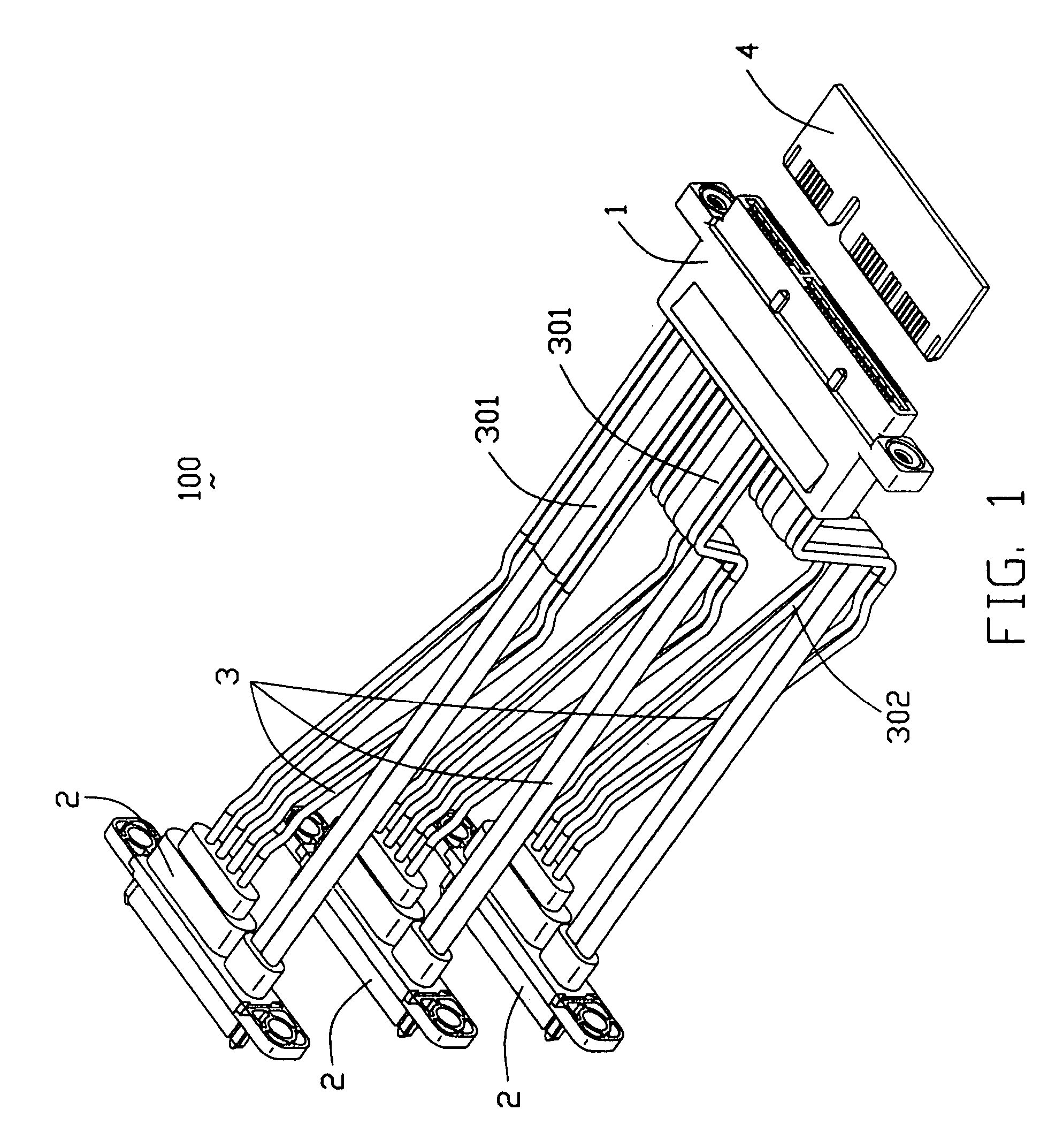
[0021]Referring to FIG. 1, a cable assembly 100 in accordance with a first preferred embodiment of the present invention comprises a first connector 1 for mating with an edge card 4, a plurality of second connectors 2 each for connecting to a complementary connector (not shown), and cable means 3 connecting the first and the second connectors 1 and 2 and comprising a plurality of sets, each terminated to one second connector 2.

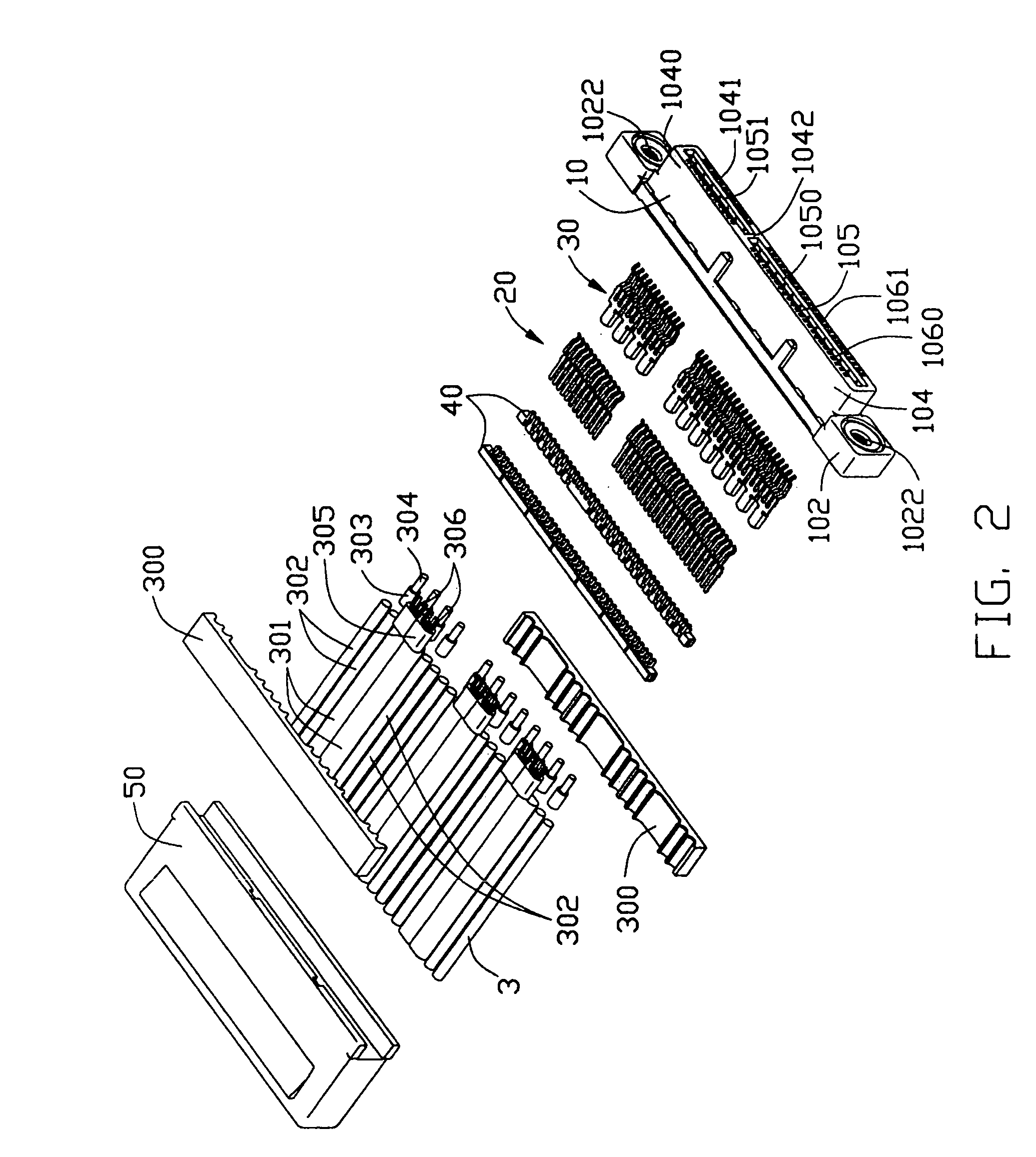
[0022]Referring to FIGS. 2–3, an exploded first connector 1, in conjunction with the cable means 3 is shown in different aspect of views. The first connector 1 comprises an first insulative housing 10, a plurality of first and second contacts 20, 30 retained in the first insulative housing 10, two spacers 40 and a cover 50.

[0023]The first housing 10 has an elongated base 102 and a mating section 104 extending perpendicularly and outwardly forming a front face of the ba...


PUM


Abstract

A cable assembly (100) includes a first connector (1), a number of second connectors (2) each having a serial advanced technology attachment interface, and cable means (3) connecting the first and the second connectors. The first connector includes a unitary first longitudinal insulative housing (10) having an upper and a lower elongated side walls (1040, 1041) opposite to each other in a lateral direction and respectively defining a plurality of first and second passageways therein, a number of signal contacts disposed in corresponding first passageways, and a number of power contacts disposed in corresponding second passageways. The cable means includes a plurality of sets of wires, each set electrically connecting with the first connector and a corresponding second connector.

Description

BACKGROUND OF THE INVENTION[0001]1. Field of the Invention[0002]The present invention relates generally to a cable assembly, and more particularly to a high speed Serial Advanced Technology Attachment (SATA) cable assembly.[0003]2. Description of the Prior Art[0004]Parallel ATA (Advanced Technology Attachment) and parallel SCSI (Small computer System Interface) are two dominant disk interface technologies in past long period. The parallel ATA disks are widely used in desktop PCs and mobile PCs, and the parallel SCSI disks are mainly used in high-volume servers and subsystems. As disk interconnect speeds continue to rise, existing parallel ATA and parallel SCSI buses are reaching their performance limits because that parallel transmissions are susceptible to crosstalk across multiple streams of wide ribbon cable that adds line noise and can cause signal errors—a pitfall that has been remedied by slowing the signal, limiting cable length or both. In view of the requirements for a high...

Claims


Application Information

Patent Timeline
Patent Type & Authority Patents(United States)
IPC IPC(8): H01R11/00
CPCH01R25/00H01R27/02H01R24/60H01R12/59H01R2107/00
Inventor WU, JERRY
Owner HON HAI PRECISION IND CO LTD
Learn More