
Pulling iron pocket, lid and shield

a technology of inserts and iron plates, applied in the field of preformed inserts, can solve the problems of allowing further leakage, pocket rigidity, and insufficient rigidity of pockets, and the flat sealing area may not always provide a completely leakproof seal

Inactive Publication Date: 2006-11-21
PENNSYLVANIA INSERT CORP
View PDF19 Cites 14 Cited by
  • Summary
  • Abstract
  • Description
  • Claims
  • Application Information

AI Technical Summary

Benefits of technology

[0009]The invention also relates to a method of over-molding a pulling iron cable. The method can involve molding one or more temporary sealing rings and applying the temporary sealing rings onto the pulling iron cable to be molded. The molding tool can be closed to crush the temporary sealing rings between the pulling iron cable and the mold tool to substantially form a seal between the inside of the tool and outside the tool. The tool can be con...

Problems solved by technology

It has been found that the flat seal area may not always provide a completely leakproof seal; and can allow some concrete slurry to seep into the pocket.
Also, the slot through which the pulling iron is inserted into the pocket may not be adequately rigid to resist deformation under pressure, potentially permitting further leakage.
Unfortunately, even when supported by Styrofoam or the like, the possibility of the pulling iron moving about inside the pocket is not eliminated.
Thus, the pulling iron can become embedded too close to the inside edge of the recess, providing an inadequate clearance area for attaching a hook to the pulling iron.
Although this innovation improved the situation, the pulling iron could still move about inside the pocket during pouring and some leakage through the slot continued to be noted.
However, these systems may not hold the iron in place well because the snaps are small, difficult to use and may not latch tightly.
Adding neoprene is costly and does not eliminate leakage of concrete into the pocket if excessive deformation occurs around the slot.

Method used


Image

  • Pulling iron pocket, lid and shield
  • Pulling iron pocket, lid and shield
  • Pulling iron pocket, lid and shield

Examples


Embodiment Construction

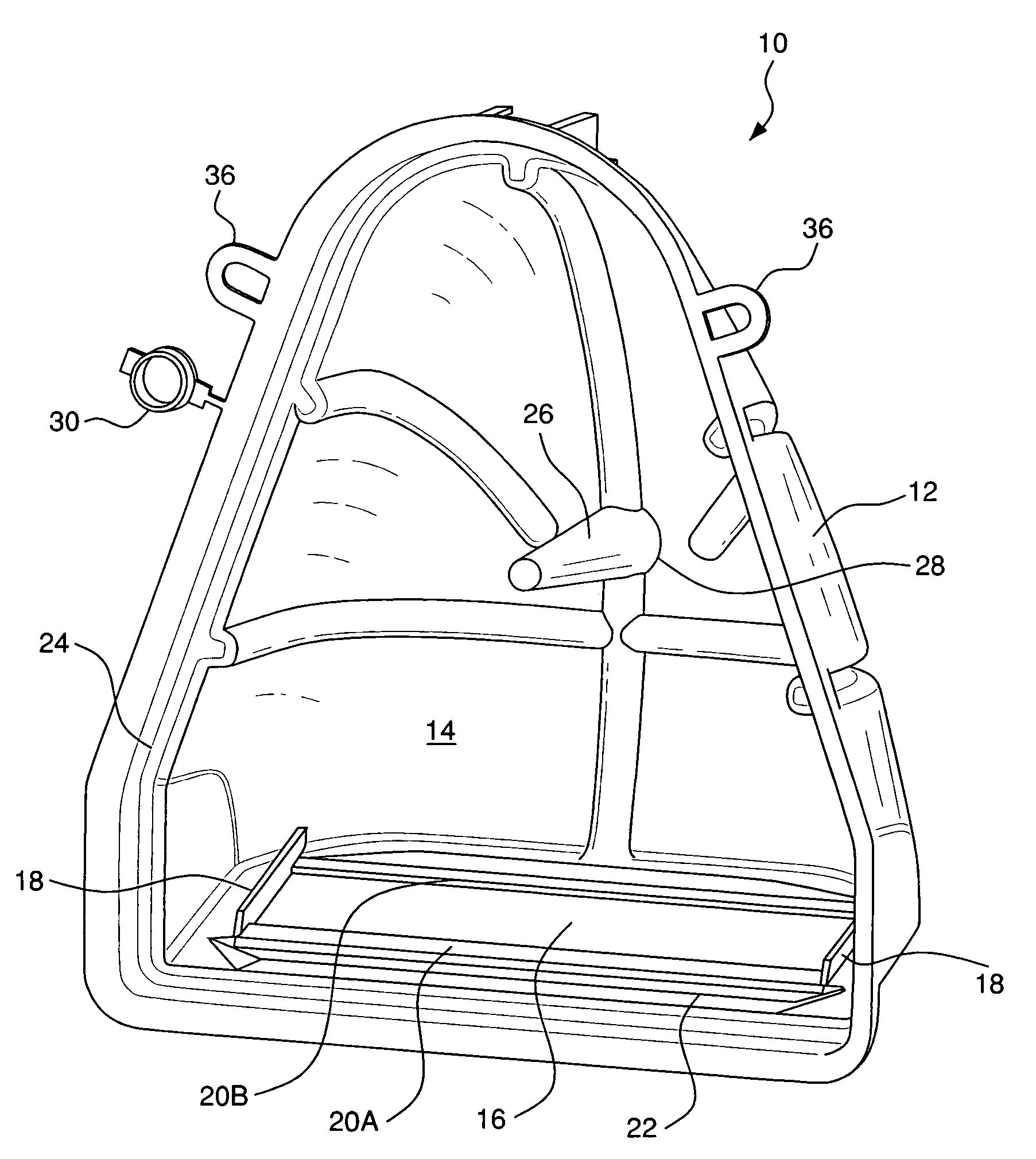
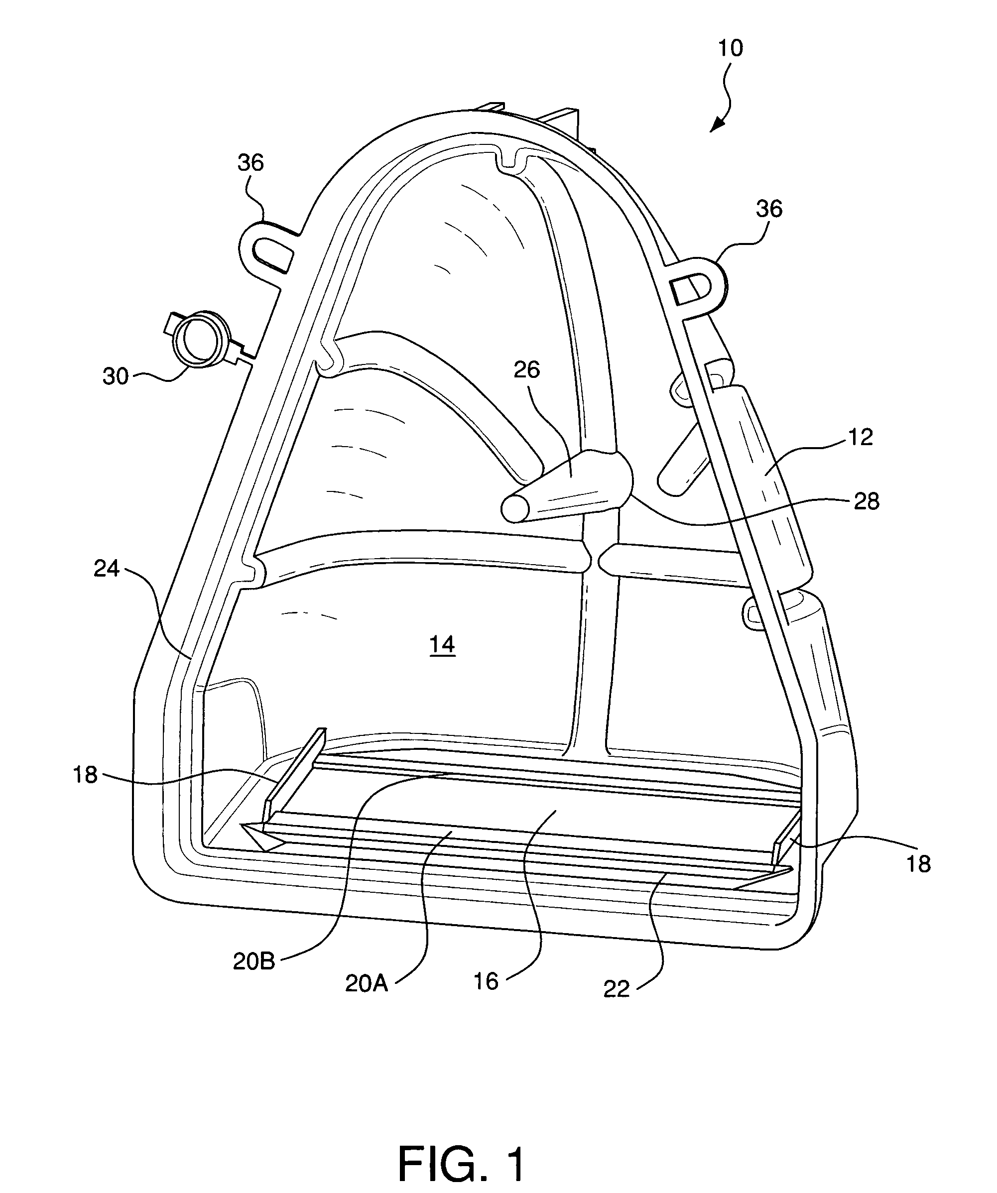
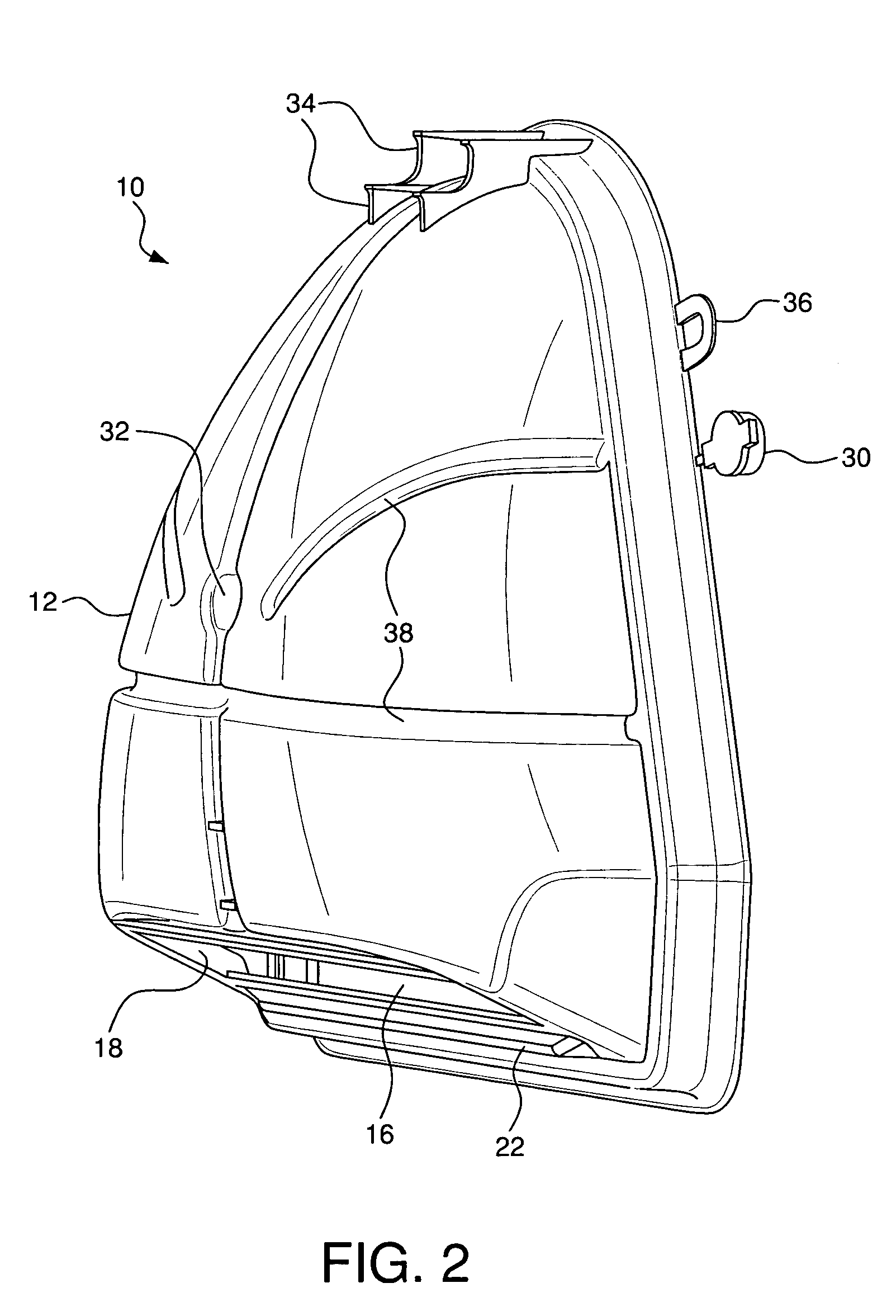
[0022]In the Figures, in which like reference numerals indicate like elements, there are shown a preferred pulling iron pocket, a lid and shields according to the present invention. FIG. 1 shows the inside of a pulling iron pocket 10. The pocket 10 includes a shell 12 having an inside 14 that defines a cavity. The shell is preferably plastic.

[0023]The bottom of the shell includes a slot 16 that is reinforced with stiffening members on at least two sides, preferably on all sides. The stiffening members can include lateral walls 18, forward rim 20A and rear rim 20B. In addition, the bottom of the pocket can be provided with a recess 22 adjacent the forward rim 20A to provide additional resistance to bending. A similar feature can be provided adjacent the rear rim 20B. Together, the stiffening members provide a substantially rigid surface surrounding the slot 16.

[0024]A groove 24 may be formed around the periphery of the front of the pocket 10. The groove 24 provides a robust snap in d...


PUM


Abstract

A pocket, lid and shield for casting a pulling iron in a concrete structure are described. The pocket includes a slot reinforced with stiffening members for receiving the pulling iron. The pocket also includes a frangible support post for supporting the pulling iron when it is received in the pocket. Also described are embodiments of a shield, which include clipping members adapted to engage the stiffening members, for covering the slot, and a lid having a lip for engaging a peripheral groove in the pocket. Methods of over-molding a pulling iron cable are also described. According to the methods, a temporary seal, which can be used in over-molding a subsequent pulling iron cable, can be formed simultaneously with each over-molded product. During molding, the cable can be held in the center of a channel in the mold tool using a retractable magnetic pin.

Description

CROSS-REFERENCE TO RELATED APPLICATION[0001]The present application claims priority from U.S. Provisional Application No. 60 / 439,014, filed Jan. 9, 2003, which is incorporated herein by reference in its entirety.FIELD OF THE INVENTION[0002]The invention relates to pre-formed inserts for use while pouring concrete and the like. More specifically, the invention relates to a pocket, lid and shield for recessing a pulling iron in a concrete structure.BACKGROUND OF THE INVENTION[0003]Pulling irons can be embedded in concrete structures to provide a hook by which a crane or other moving device can grab and manipulate the structure. In the field, the pulling iron can also be used to attach a pulley for pulling cables or wires through a conduit into the structure using a winch. Such pulling irons can be confined to a recess formed in the concrete so as not to protrude past the wall of the structure.[0004]A pulling iron pocket is used to form the recess in the concrete structure. A known pul...

Claims


Application Information

Patent Timeline
IPC IPC(8): E04G13/02E04G9/10B28B23/00B29C33/16B29C45/14E04G15/04E04G21/14
CPCB29C45/14073E04G15/04E04G21/142B28B23/0056B29C33/16
Inventor SACK, JAMES A.
Owner PENNSYLVANIA INSERT CORP
Learn More