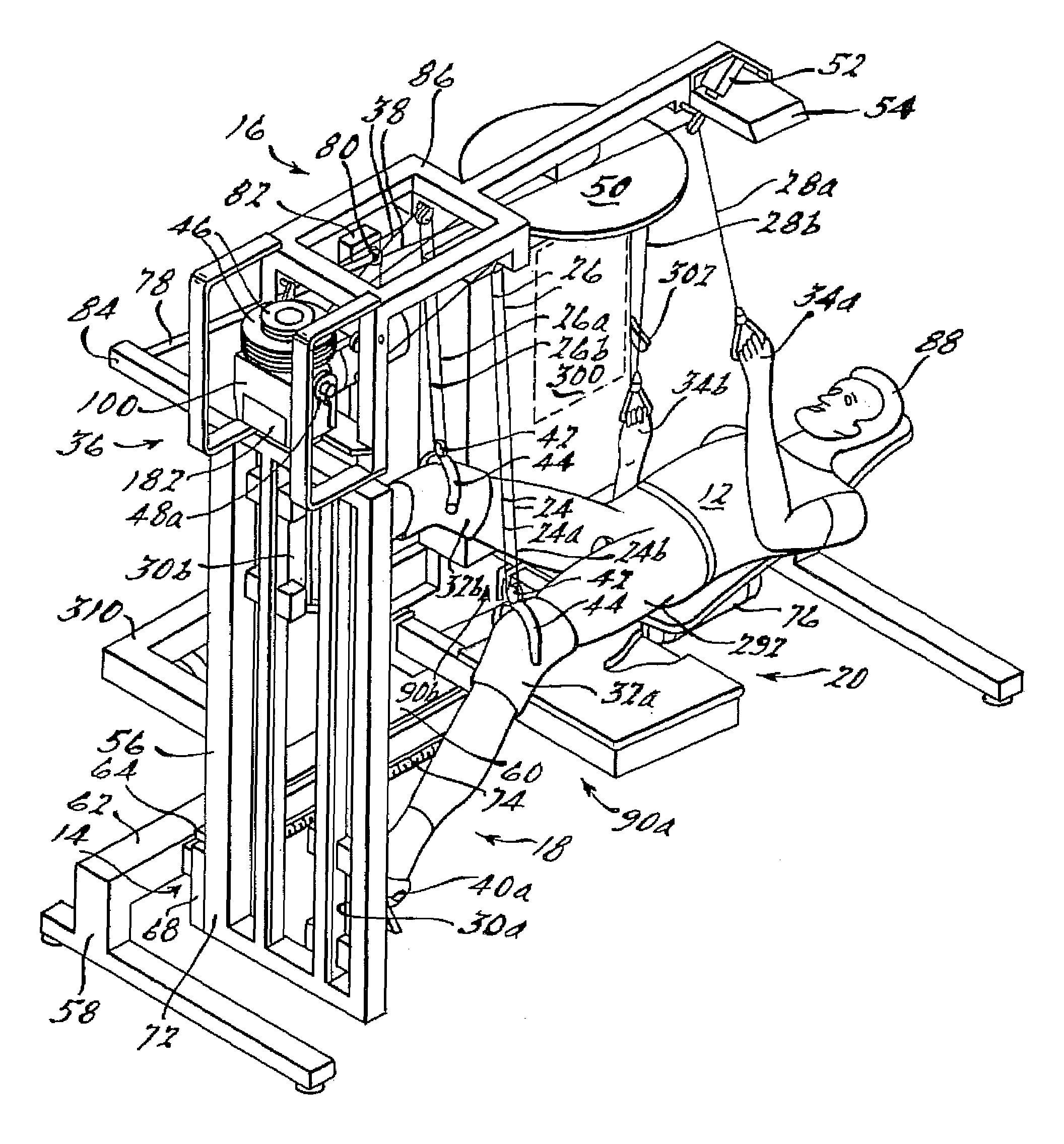
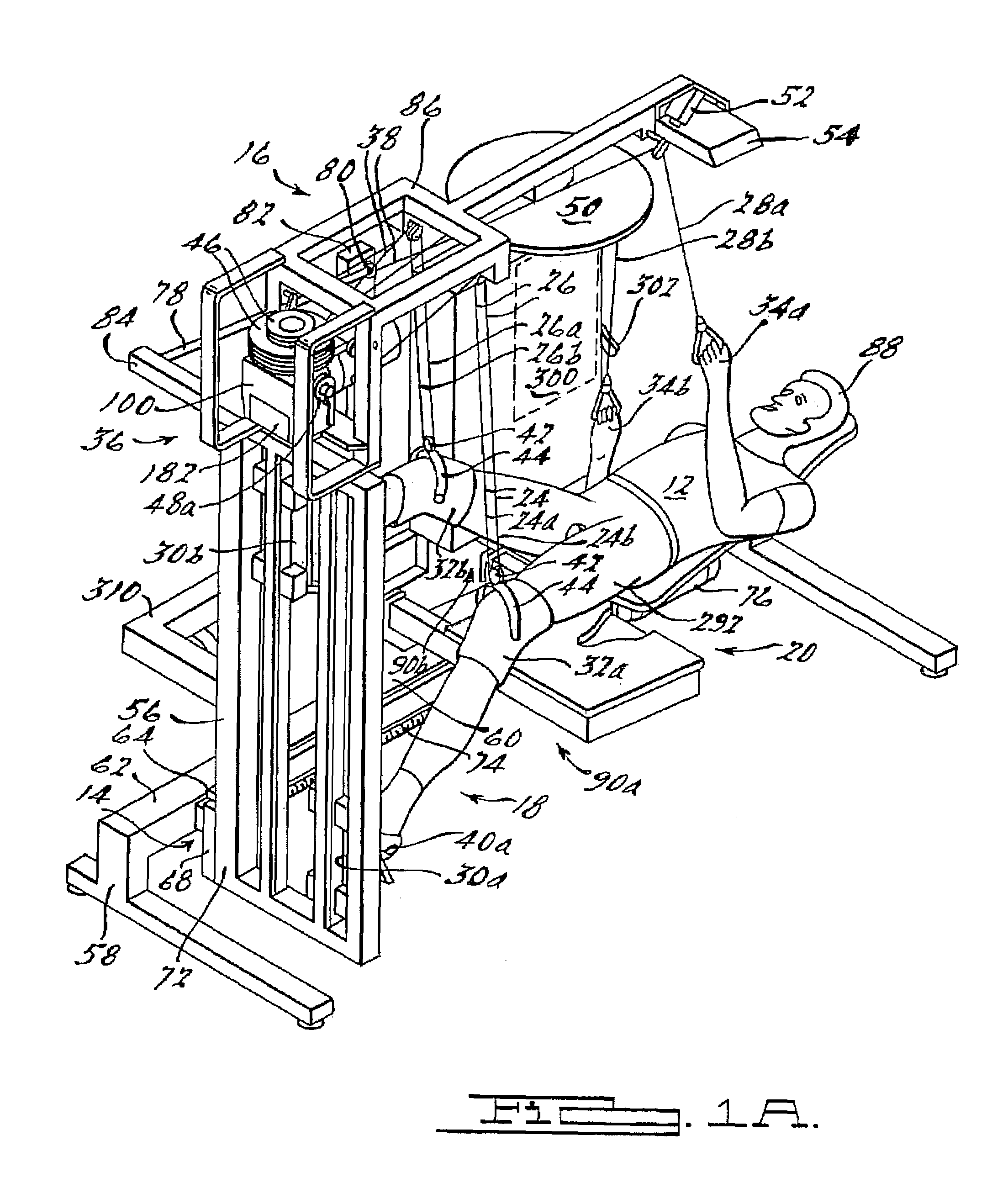
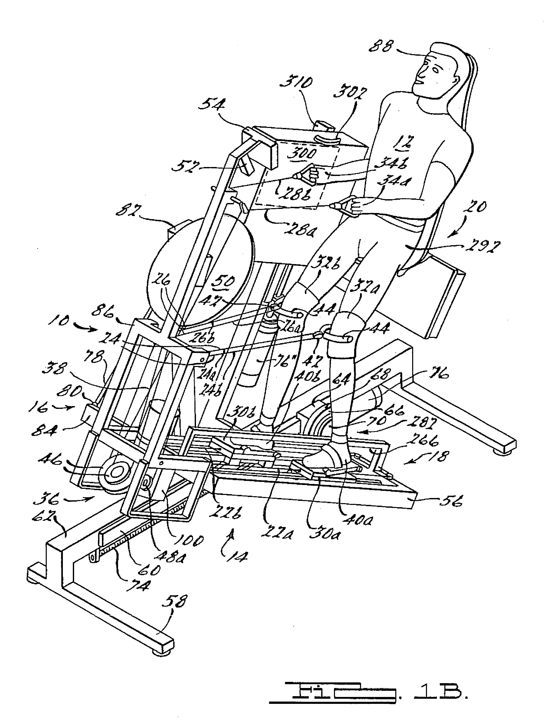
[0008]These and other objects are achieved via utilization of walking motion apparatus presented in a preferred embodiment of the present invention by a supinely disposed patient in implementing a substantially normal walking motion while supporting a selected portion of his or her weight. Also respectively presented in first, second, third and, fourth alternate embodiments are elevation drive, rhythmic limb elevation drive, foot guiding, and patient handling mechanisms therefor. Further, presented in a fifth alternate preferred embodiment of the present invention are methods for improving cardiovascular circulation, growing high quality muscle mass, supporting selected portions of such a patient's own weight, and even of enabling that patient to fire muscle groups normally utilized in walking. As is more fully explained below, the walking motion apparatus is configured such that a wheel chair bound individual can utilize it in all respects without assistance, and such that even a quadriplegic or severely brain injured individual can utilize it with minimal assistance. For convenience in further discussion however, utilization of the walking motion apparatus is assumed to be by a wheel chair bound individual having nominal use of his or her hands and arms (hereinafter “patient”) unless its use by a quadriplegic or severely brain injured individual is specifically indicated.
[0016]Finally, methods for improving a patient's cardiovascular circulation, growing high quality muscle mass, and even of firing muscle groups normally utilized in walking are presented in a fifth alternate preferred embodiment of the present invention. These methods are implemented in conjunction with utilization of a walking motion apparatus comprising at least the rhythmic limb elevation drive and foot guiding mechanisms wherein a supinely disposed patient can affect a substantially normal walking motion, and wherein a first and most general method comprises the steps of: the patient donning appropriate knee braces comprising hinged bails; positioning the patient in the supine position under the rhythmic limb elevation drive mechanism; positioning and affixing the patient's shoes upon left and right articulated slide assemblies comprised in the foot guiding mechanism; attaching first and second limb groups each including one of the hinged bails and an opposing hand to first and second sets of pulley-supported lines comprised in the rhythmic limb elevation drive mechanism; and activating a rhythmic limb elevation drive unit comprised in the rhythmic limb elevation drive mechanism at a selected walking frequency.
[0027]In a ninth aspect, the present invention is directed to the walking motion apparatus of the eighth aspect wherein the pivoting seat back and pivoting mechanism comprise: a transverse pivot axis about which the seat back pivots that is located in a relatively elevated manner such that adequate clearance is provided for ensuing leg motion during the walking exercise after seat back is rotated into a horizontal position; a transverse hip axis constrained for powered motion along a nominally vertical axis such that the distance between a patient's hips and a foot guiding mechanism remains nominally constant as the seat back is elevated; a longitudinally oriented short stroke slide component for slidingly mounting the seat back along a longitudinal axis in order to accommodate normal up-and-down motions that a patient experiences during a walking exercise; and a powered slide assembly for adjustably coupling the pivoting mechanism to the angularly elevating frame along the longitudinal axis for appropriately locating the patient's hips with respect to the foot guiding mechanism.
[0028]In a tenth aspect, the present invention is directed to a method for improving a paraplegic or quadriplegic patient's cardiovascular circulation, growing high quality muscle mass, and even of firing muscle groups normally utilized in walking, wherein the method is implemented in conjunction with utilization of a walking motion apparatus comprising at least rhythmic limb elevation drive and foot guiding mechanisms wherein a supinely disposed such patient can affect a substantially normal walking motion, and wherein the method comprises the steps of: the patient donning appropriate knee braces comprising hinged bails; positioning the patient in the supine position under the rhythmic limb elevation drive mechanism; positioning and affixing the patient's shoes upon left and right articulated slide assemblies comprised in the foot guiding mechanism; attaching first and second limb groups each including one of the hinged bails and an opposing hand to first and second sets of pulley-supported lines comprised in the rhythmic limb elevation drive mechanism; and activating a rhythmic limb elevation drive unit comprised in the rhythmic limb elevation drive mechanism at a selected walking frequency.
[0030]In a twelfth and final aspect, the present invention is directed to a method for improving a paraplegic or quadriplegic patient's cardiovascular circulation, growing high quality muscle mass, and even of firing muscle groups normally utilized in walking, wherein the method is implemented in conjunction with utilization of a walking motion apparatus comprising rhythmic limb elevation drive, foot guiding, elevation drive and patient handling mechanisms whereby the patient can, without assistance, set up and get into the walking motion apparatus, properly attach him- or herself to the rhythmic limb elevation drive mechanism and operate the walking motion apparatus in order to achieve a substantially normal walking motion while supported in a selectively elevated supinely disposed position, and wherein the method comprises the patient performing the steps of: positioning the elevation drive mechanism to an intermediate position whereat he or she can conveniently open the rhythmic limb elevation drive unit comprised in the rhythmic limb elevation drive mechanism even while being wheelchair bound; opening the rhythmic limb elevation drive unit; setting stroke length; closing the rhythmic limb elevation drive unit; resetting the elevation drive mechanism to its base position; moving to a position laterally proximate to a pivoting seat back and seating platform comprised in the patient handling mechanism and located generally under the rhythmic limb elevation drive mechanism; moving onto the seating platform in a centered position whereat the patient is positioned against the seat back and astride a “horn” portion thereof nestled within a pocket formed in the seating platform; moving the patient handling mechanism forward, and if desired, rotating the pivoting seat back to locations whereat the patient can conveniently position his or her shoes upon the left and right articulated slide assemblies; positioning and affixing his or her shoes thereon; attaching first and second sets of knee elevating pulley-supported lines to the hinged bails; moving the patient handling mechanism to a location sufficiently removed from the foot guiding mechanism for optimizing the intended walking motion; rotating the seat back into a horizontal position whereat the patient is located supinely with his or her thighs straddling the horn portion of the seat back and thus keeping him or her centered thereon during the ensuing walking exercise; activating and positioning the elevation drive mechanism at the angular elevation whereat the selected portion of the patient's weight is self supported; presetting the rhythmic limb elevation drive unit comprised in the rhythmic limb elevation drive mechanism at the selected walking frequency; grabbing first and second arm elevating pulley-supported lines; and activating the rhythmic limb elevation drive unit at the selected walking frequency.


