Refrigerator and temperature sensor fixing method in the refrigerator

a technology of temperature sensor and fixing method, which is applied in the direction of domestic cooling apparatus, lighting and heating apparatus, support, etc., can solve the problems of dispersion of the sensed temperature and degradation of the temperature sensing performance, and achieve the effect of rapid and accurate control of the temperature of the sensor

Inactive Publication Date: 2006-11-28
LG ELECTRONICS INC
View PDF11 Cites 11 Cited by
  • Summary
  • Abstract
  • Description
  • Claims
  • Application Information

AI Technical Summary

Benefits of technology

[0015]The present invention has been made in view of the above mentioned problems involved with the related art, and an object o...

Problems solved by technology

In this case, there may be problems of a degradation in tempe...

Method used


Image

  • Refrigerator and temperature sensor fixing method in the refrigerator
  • Refrigerator and temperature sensor fixing method in the refrigerator
  • Refrigerator and temperature sensor fixing method in the refrigerator

Examples


second embodiment

[0057]Referring to FIG. 6, a temperature sensor according to the present invention is illustrated.

[0058]The temperature sensor shown in FIG. 6 includes a heat transfer member 80 having a rectangular cross-sectional structure in which one of its four side surfaces 80a to 80d, that is, the side surface 80a, is in surface contact with the inner casing 54.

[0059]In this temperature sensor, the side surface 80a of the heat transfer member 80 provides the surface contact area S to be in surface contact with the inner casing 54. The remaining three side surfaces 80b to 80d are surrounded by the insulator 64.

third embodiment

[0060]Referring to FIG. 7, a temperature sensor according to the present invention is illustrated.

[0061]The temperature sensor shown in FIG. 7 includes a heat transfer member 90 having a semicircular cross-sectional structure in which its flat side surface 90a is in surface contact with the inner casing 54.

[0062]In this temperature sensor, the side surface 90a of the heat transfer member 90 provides the surface contact area S to be in surface contact with the inner casing 54. The remaining surfaces of the heat transfer member 90 are surrounded by the insulator 64.

first embodiment

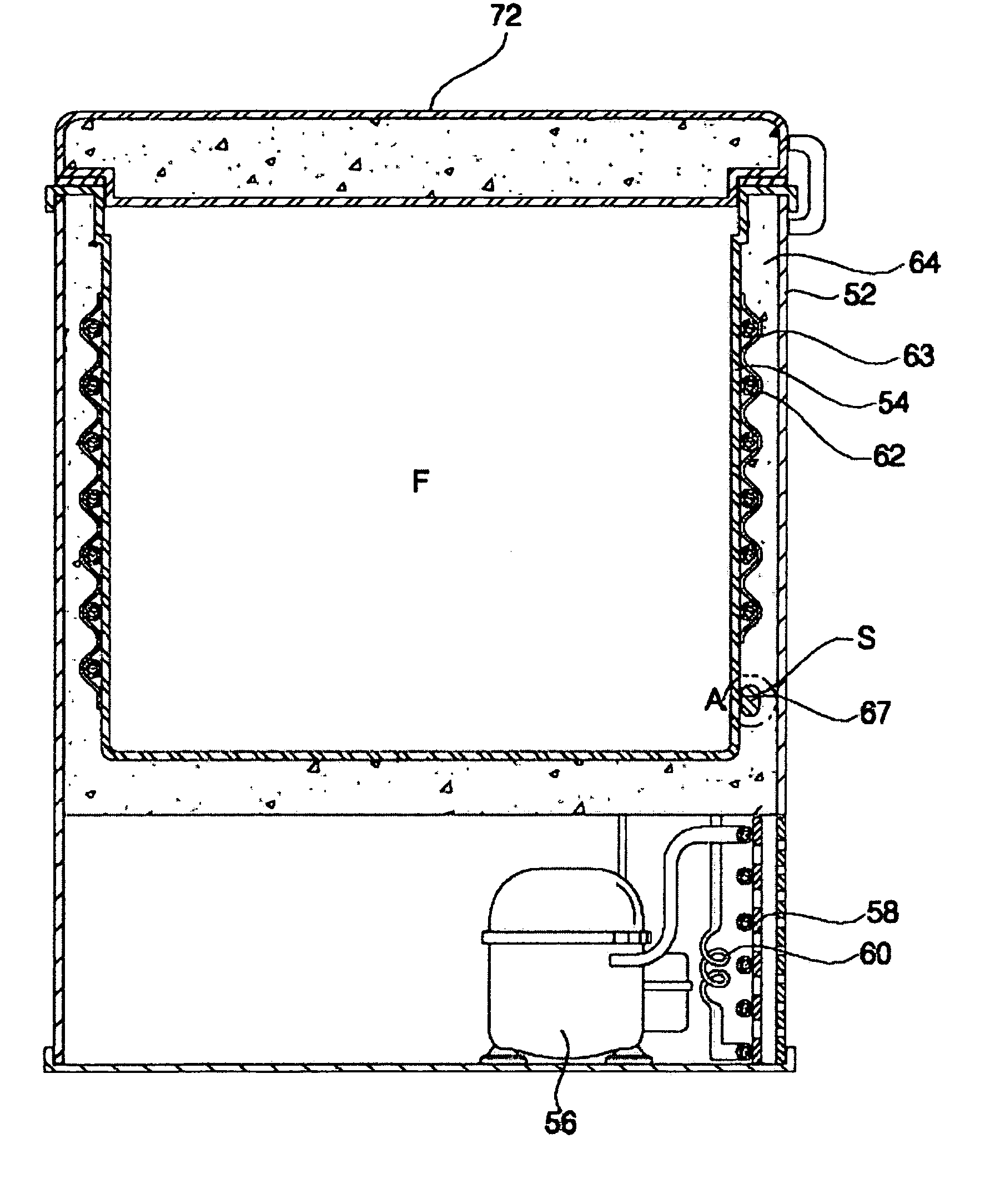
[0063]FIG. 8 illustrates a temperature sensor fixing method in the direct cooling type refrigerator according to the present invention. FIG. 9 is an enlarged sectional view illustrating the temperature sensor of the direct cooling type refrigerator according to the present invention which is not in a fixed state yet.

[0064]In accordance with the temperature sensor fixing method, the surface contact area S adapted to come into contact with the inner casing 54 is first formed at the temperature sensor 66 (S1).

[0065]This first step includes a first procedure of forming the heat transfer member 67 such that it is flat at at least one side surface thereof, that is, the side surface 67a, and a second procedure of fixing the formed heat transfer member 67 to the thermistor 68.

[0066]The first procedure is achieved by injection-molding the heat transfer member 67 in a mold formed with a flat surface corresponding to the flat side surface 67a, by use of a melt synthetic resin, and then solidif...


PUM


Abstract

A direct cooling type refrigerator capable of rapidly and accurately controlling the temperature thereof, reducing the ON/OFF time of its compressor, thereby preventing the temperature deviation of its storage compartment from increasing over a predetermined value. The refrigerator includes an outer casing defining an appearance of the refrigerator, an inner casing arranged within the outer casing, and defined with a storage compartment, an insulator interposed between the outer casing and the inner casing, a compressor for compressing a refrigerant, an evaporator arranged to be in contact with the inner casing, and adapted to cool the inner casing in accordance with evaporation of a refrigerant passing therethrough, a temperature sensor provided with a surface contact area closely contacting the inner casing, and adapted to sense a temperature of the inner casing, and a control unit for controlling the compressor in accordance with the temperature sensed by the temperature sensor.

Description

[0001]This nonprovisional application claims priority under 35 U.S.C. § 119(a) on Patent Application No. 10-2003-0016577 filed in Korea on Mar. 17, 2003, which is herein incorporated by reference.BACKGROUND OF THE INVENTION[0002]1. Field of the Invention[0003]The present invention relates to a direct cooling type refrigerator, and more particularly to a direct cooling type refrigerator in which the contact area between an inner casing defined with a storage compartment and a temperature sensor is large so that the temperature sensor can accurately and rapidly sense a variation in the temperature of the storage compartment, thereby reliably controlling a compressor. Also, the present invention relates to a temperature sensor fixing method in such a direct cooling type refrigerator.[0004]2. Description of the Related Art[0005]Generally, refrigerators may be classified, in terms of their cooling systems, into a direct cooling type refrigerator, in which its inner casing defined with a ...

Claims


Application Information

Patent Timeline
IPC IPC(8): F25B1/00F25B49/00F25D25/00F25D23/00F25D11/00F25D23/06F25D29/00
CPCF25D23/061F25B2339/023F25D29/005F25D2400/10F25D2700/10F25D29/00
Inventor LEE, TAE HEEKIM, KYUNG SIKKIM, YANG GYUKIM, SE YOUNGCHUN, CHAN HOLEE, YOUN SEOK
Owner LG ELECTRONICS INC
Why Eureka
Try Eureka