
Apparatus and method for controlling focus jump between recording layers in high-density multi-layer disk

a multi-layer disk and recording layer technology, applied in the direction of recording information storage, instrumentation, disposition/mounting of heads, etc., can solve the problems of poor fe signal with respect to the first recording layer lb>0, difficult to detect the time when a focus pull-in is performed, and increase the risk of failing the focus jump. achieve the effect of rapid and accurate control of the focus jump

Inactive Publication Date: 2008-04-17
SAMSUNG ELECTRONICS CO LTD
View PDF6 Cites 4 Cited by
  • Summary
  • Abstract
  • Description
  • Claims
  • Application Information

AI Technical Summary

Benefits of technology

[0015]Aspects of the present invention provide an apparatus and method of rapidly and accurately controlling a focus jump between recording layers in a high-density multi-layer disk.

Problems solved by technology

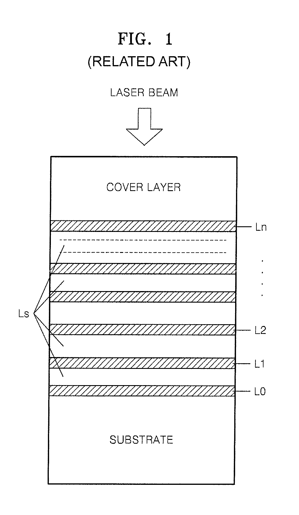
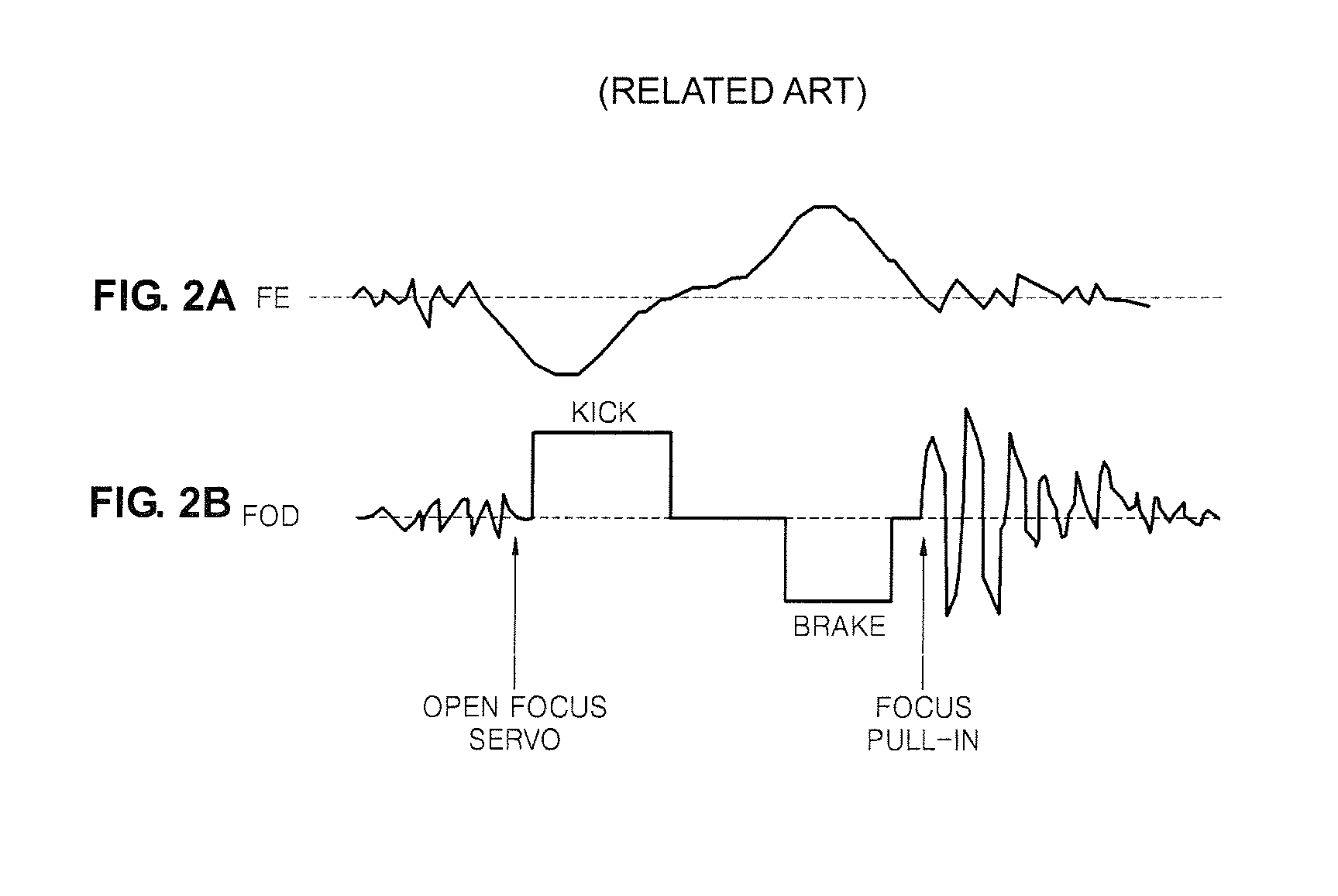
When a focus jump is performed from the first recording layer, which is a current recording layer, to the third recording layer, which is a target recording layer, since the third FE signal FE2 of the third recording layer L2 is poor, distorted, or degraded, detecting a time when a focus pull-in is performed is difficult.
As such, the risk of failing the focus jump is increased.
However, as spherical aberration of the third recording layer L2 is corrected, the spherical aberration of the first recording layer L0 increases, thereby resulting in a poor FE signal with respect to the first recording layer L0.
At this time, if focusing servo control is maintained, focus servo becomes unstable.
Such problems may become serious when a thickness difference between intermediate layers of the multi-layer disk is high or the velocity of a spherical aberration correcting unit, such as a lens driving motor, is low.
If a focus jump is performed at this time, the focus jump cannot be performed in a kick and brake manner.
That is, while the aberration of the third recording layer L2 is corrected during the focus jump, the FE signal of the first recording layer L0 becomes poor, servo control is unstable, and much time is consumed to correct the aberration due to the large thickness of the spacer layers Ls, thereby causing the optical pickup and the actuator to drop.
In this case, discontinuities may occur while recording or reproducing information, and, particularly in the case of the disk having a high deflection, the FE signal may be distorted during the spherical aberration correction of the target recording layer with the result being that the disk and the objective lens may collide with each other during vertical movement of the actuator.

Method used


Image

  • Apparatus and method for controlling focus jump between recording layers in high-density multi-layer disk
  • Apparatus and method for controlling focus jump between recording layers in high-density multi-layer disk
  • Apparatus and method for controlling focus jump between recording layers in high-density multi-layer disk

Examples


Embodiment Construction

[0037]Reference will now be made in detail to the present embodiments of the present invention, examples of which are illustrated in the accompanying drawings, wherein like reference numerals refer to the like elements throughout. The embodiments are described below in order to explain the present invention by referring to the figures.

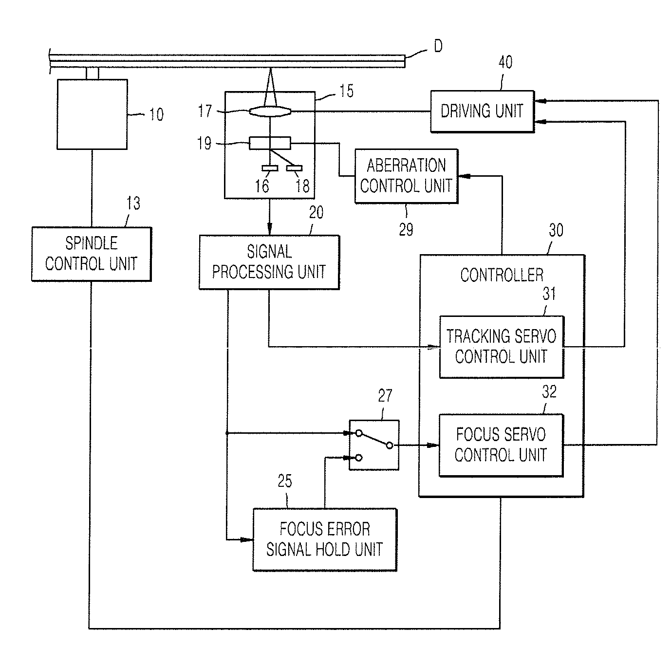
[0038]An apparatus to control a focus jump according to aspects of the present invention includes a focus hold unit that locks a focus servo for a current recording layer before a focus jump is performed to rapidly and accurately perform the focus jump from the current recording layer to another recording layer in a high density multi-layer disk using an objective lens with a high numerical aperture (NA).

[0039]FIG. 4 is a block diagram of an apparatus to control a focus jump between recording layers according to an embodiment of the present invention. The apparatus includes an optical pickup 15 including an objective lens 17 that focuses light onto a d...


PUM

PropertyMeasurementUnit
densityaaaaaaaaaa
frequencyaaaaaaaaaa
timeaaaaaaaaaa

Abstract

An apparatus and method for controlling a focus jump between recoding layers in a high-density multi-layer disk. The apparatus includes: an optical pickup including an objective lens focusing light on the disk, an aberration correcting unit, and a photodetector detecting light reflected from the disk; a signal processing unit generating a focus error signal from a signal output by the photodetector; a focus hold unit holding a focus servo of the optical pickup; a focus servo control unit controlling the focus servo of the optical pickup using the focus error signal; and a driving unit driving the optical pickup using a signal output by the focus servo control unit.

Description

CROSS-REFERENCE TO RELATED PATENT APPLICATION[0001]This application claims the benefit of Korean Patent Application No. 2006-98867, filed Oct. 11, 2006 in the Korean Intellectual Property Office, the disclosure of which is incorporated herein by reference.BACKGROUND OF THE INVENTION[0002]1. Field of the Invention[0003]Aspects of the present invention relate to an apparatus and method of controlling a focus jump between recording layers in a high-density multi-layer disk using an objective lens having a high numerical aperture and a light source emitting light that has a short wavelength.[0004]2. Description of the Related Art[0005]In general, optical disks are widely used as information recording media for optical pickups that record and / or reproduce information without contacting the optical disk. Optical disks are classified into compact disks (CDs) and digital versatile disks (DVDs) according to information recording capacity. Furthermore, high definition-digital versatile disks ...

Claims


Application Information

Patent Timeline
Patent Type & Authority Applications(United States)
IPC IPC(8): G11B7/00G11B7/085
CPCG11B7/08511G11B2007/0013G11B7/13925G11B7/09G11B7/095
Inventor KIM, SUNG-HYUNPARK, YOUNG-JAEOTSUKA, TATSUHIROJEONG, KAB-HYUN
Owner SAMSUNG ELECTRONICS CO LTD
Learn More