Connector restraint device

a technology of restraint device and connector, which is applied in the direction of coupling device connection, coupling parts engagement/disengagement, incorrect coupling prevention, etc., can solve the problems of equipment or system disruption or damage, and it is not economical to connect only one cable or possibly even a pair of cables

Active Publication Date: 2006-11-28
PULIZZI ENG
View PDF36 Cites 91 Cited by
  • Summary
  • Abstract
  • Description
  • Claims
  • Application Information

AI Technical Summary

Problems solved by technology

Accidental disconnection of some of the cables may thus occur, often causing equipment or system disruption or damage.
The disclosed connector restraint device is especially useful for restraining a number of cables connected at a rear chassis wall of an single piece of electrical equipment; however, it would not be economical for retraining only one cable, or possibly even a pair of cables, connected, for example, for supplying power to a single piece of electrical equipment.

Method used


Image

  • Connector restraint device
  • Connector restraint device
  • Connector restraint device

Examples


Embodiment Construction

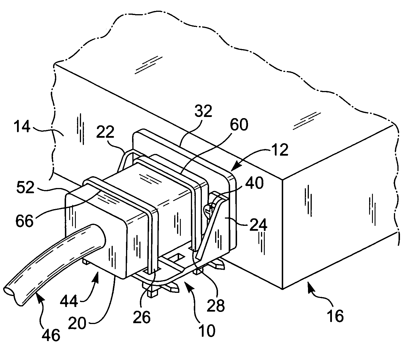
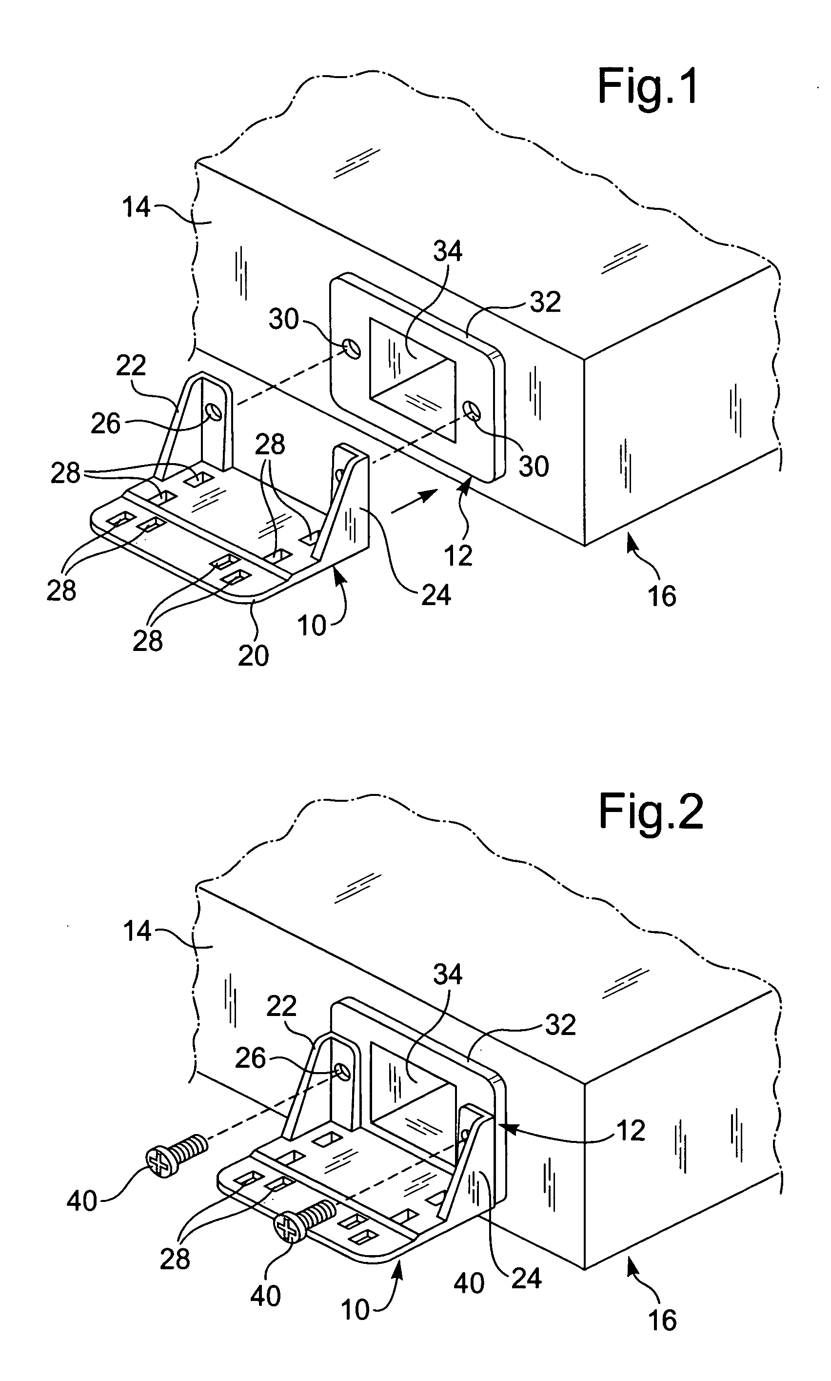
[0026]FIG. 1 is a perspective drawing showing a restraint device 10 according to the present invention in a position for attachment at a male inlet connector 12 installed in a rear wall 14 of an electrical equipment chassis 16 (only portions of which are shown; inlet connector 12 may be an IEC 60320-C20 or -C14; restraint device 10 is shown comprising a flat base portion 20 having two attachment ears 22 and 24 extending upwardly therefrom at a forward region thereof, each of such ears having an attachment aperture 26 formed therethrough (only the aperture in each 22 being shown), and further showing a number of apertures 28 formed through the base portion sized for receiving conventional nylon cable ties (not shown); two chassis attachment apertures 30 being shown in a front region 32 of the inlet connector 12 to either side of a central female plug receiving opening 34;

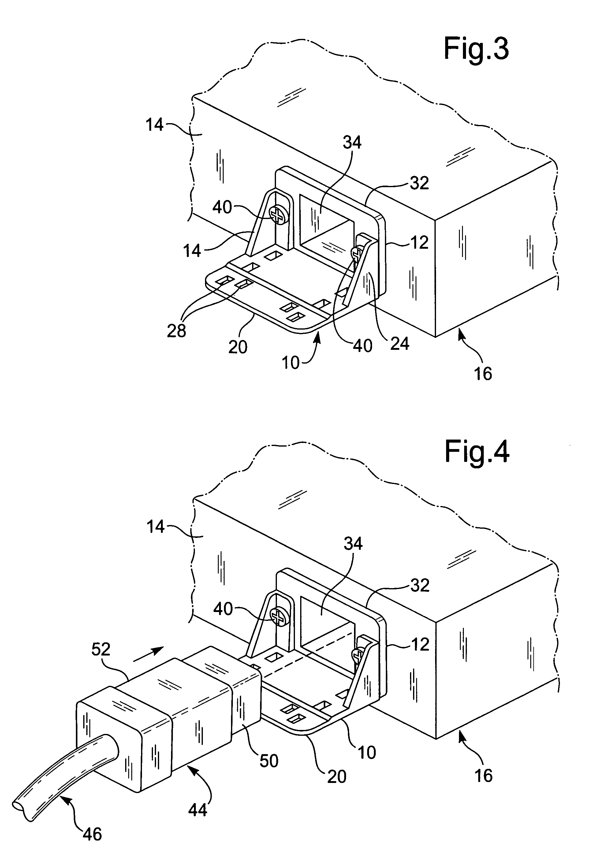
[0027]FIG. 2 is a perspective drawing showing ears 22 and 24 of restraint device 10 positioned against front regio...


PUM


Abstract

Electrical plug restricting apparatus includes a male inlet connector fixable to an electrical equipment chassis, a restraint device attachable to the connector and including a plug supporting base, the base having apertures therethrough, and at least one plug securing cable tie insertable through the base aperture and having a length sufficient to surround the plug, the tie securing the plug to the base when tightened.

Description

[0001]The present application claims priority from U.S. Ser. No. 60 / 604,519 filed Aug. 26, 2004. This application is to be incorporated in its entirety by this specific reference thereto.FIELD OF INVENTION[0002]The present application relates generally to the field of electrical equipment, more particularly to connector restraint devices and still more particularly to power cord connector restraint devices.BACKGROUND OF THE INVENTION[0003]Individual pieces of electrical equipment used in large electrical systems, such as computer server systems, are typically rack mounted in bays. Many of these pieces of electrical equipment have a number of electrical connections for intercommunication, and virtually all, if not all, have connections by which power is supplied to the equipment, such connections almost always being at a rear wall of the equipment enclosures (chassis).[0004]As a consequence, a bay of electrical equipment may have a great many exposed electrical cables which must be c...

Claims


Application Information

Patent Timeline
Patent Type & Authority Patents(United States)
IPC IPC(8): H01R13/62
CPCH01R13/5804H01R13/639H01R13/6395H01R13/74
Inventor PULIZZI, PETER S.VANDER VORSTE, MICHAEL D.
Owner PULIZZI ENG
Why Eureka
Try Eureka