Planar coil and contactless electric power transmission device using the same

US20100277004A1Inactive Publication Date: 2010-11-04PANASONIC CORP

Image

  • Planar coil and contactless electric power transmission device using the same
  • Planar coil and contactless electric power transmission device using the same
  • Planar coil and contactless electric power transmission device using the same

Examples


first embodiment

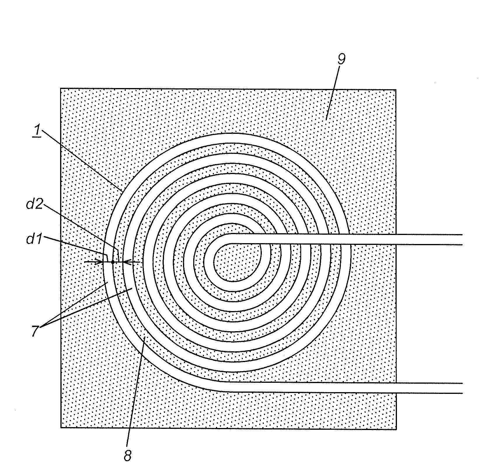
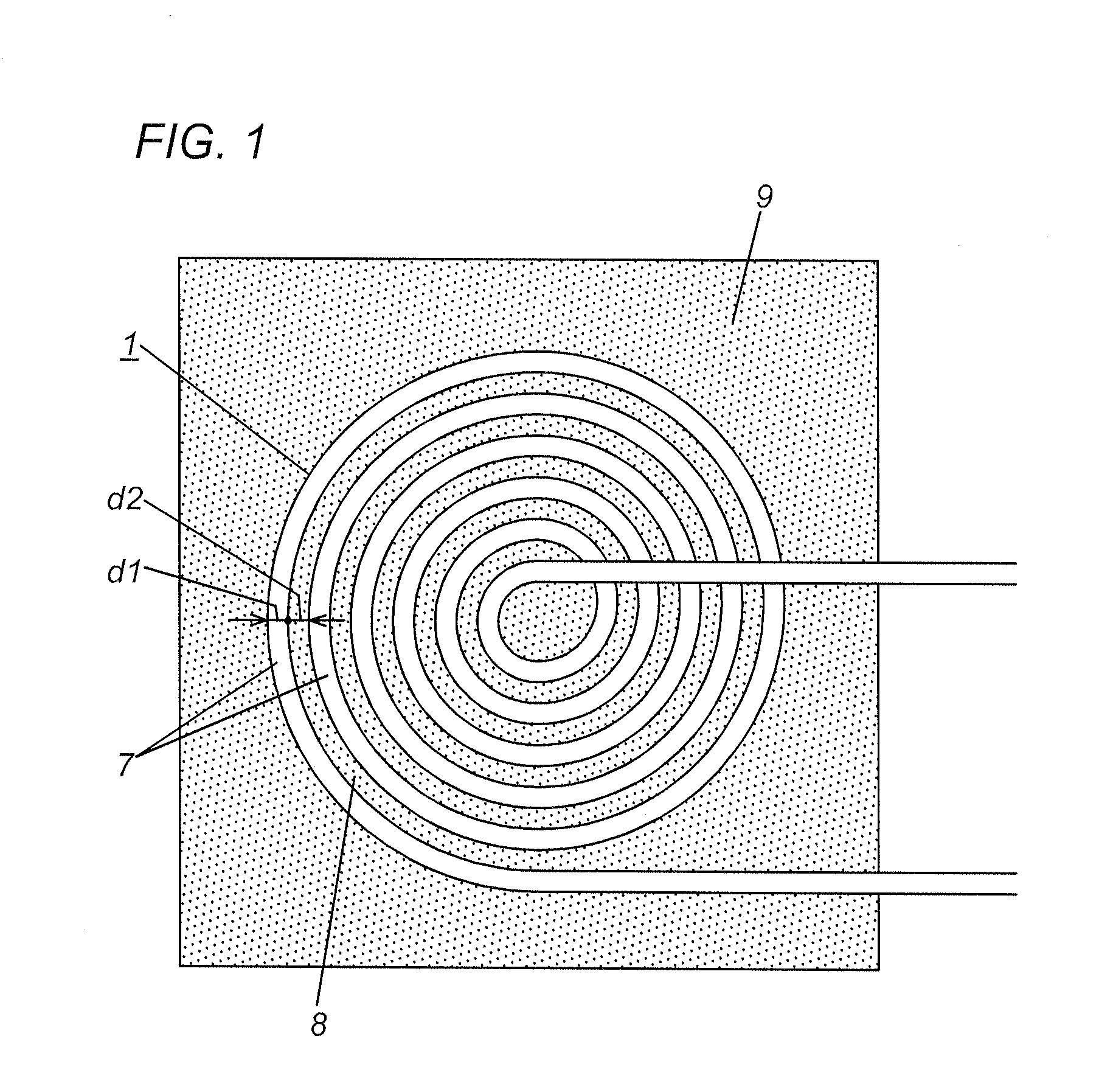
[0020]Hereafter, explanations are given as to a planar coil in this embodiment, with reference to FIGs. FIG. 1 shows a planar coil 1 in this embodiment. Each of FIGS. 2 and 3 shows a contactless electric power transmission device 50 using this planar coil 1.

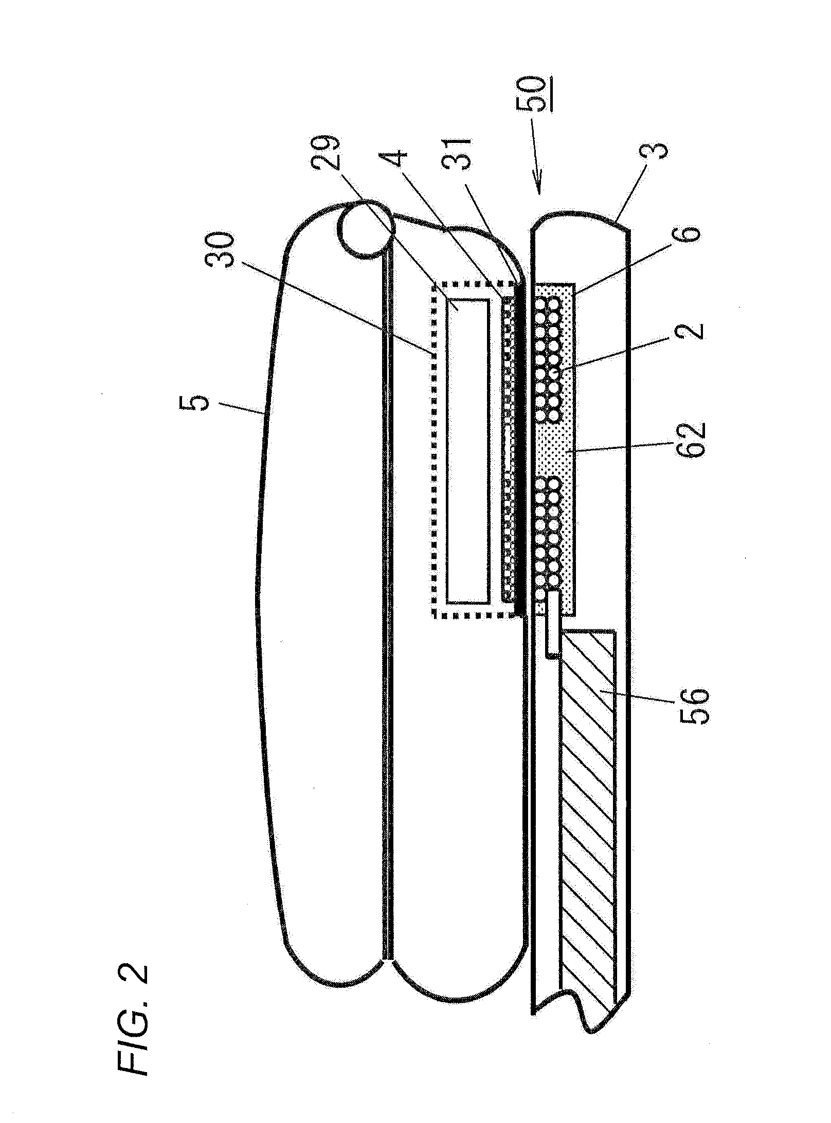
[0021]This contactless electric power transmission device 50 comprises a recharger 3 having a power transmission coil 2 and a main body 5 having a power receiving coil 4. The main body 5 in FIG. 2 is a mobile phone. As shown in FIG. 3, the recharger 3 includes a rectifying and smoothing circuit 51, a voltage conversion circuit 52, an oscillation circuit 53, a display circuit 54, a control circuit 55, and the power transmission coil 2. The main body 5 includes the power receiving coil 4, a rectifying circuit 27, a control circuit 28, and a load L mainly made of secondary battery 29. A component indicated by 56 in FIG. 2 is a printed substrate mounting thereon the circuits 51 to 55. A component indicated by 6 is a power transmissio...

second embodiment

[0028]Hereafter, explanations are given as to different components of the planar coil 1 in this embodiment. Like parts as those in the planar coil 1 in the first embodiment are designated by like reference numerals, and no duplicate explanation deemed necessary.

[0029]FIGS. 5 and 6 show the planar coils 1 in this embodiment. In fabrication of this planar coil 1, the wire 7 is automatically coiled into spiral configuration around a wining shaft 10 of the wining apparatus. The wining shaft 10 is disposed to project from the rotation center of a smooth surface 11a of the rotation disc 11. As the wining shaft 10 and the rotation disc 11 rotate while the wire 7 is fixed at its one end, the wire 7 is automatically coiled on the smooth surface 11a of the disc 11 around the wining shaft 10.

[0030]As shown in FIG. 5, a plurality of (three in this embodiment) filaments 7a are bundled and coiled with a single insulative fiber 12 such that a set of the filaments 7a and the single insulative fiber...


PUM


Abstract

This invention has an object to a planar coil, a contactless electric power transmission device using the same. This planar coil is configured to suppress an eddy current developed between adjacent turns of wire for minimizing adverse effects on ambient electrical appliances resulting from heat generation. The planar coil 1 in the present invention is formed of spiral shaped wire 7 coated with thinned insulative film, in which adjacent turns of the wire 7 are spaced in radial direction at such a predetermined interval to suppress an eddy current. This planar coil 1 is preferably employed as a power transmission coil or power receiving coil.

Description

TECHNICAL FIELD[0001]This invention relates to a planar coil made of spiral-shape wire, a contactless electric power transmission device using the same.BACKGROUND ART[0002]In recent years, many contactless charging devices are widely available. Each of these contactless charging devices is equipped with a main body and a charger for contactlessly charging the main body. Each of these contactless charging devices includes a power transmission coil in the charger and a power receiving coil in the main body, and is configured to transmit the electric power to the main body from the charger through electromagnetic induction developed between these coils.[0003]In general, this main body has been applied to cordless telephone, shaver, toothbrush, or the like. This main body can be also applied to cellular phone terminal device, or the like, as proposed in Japanese unexamined patent application publication 2006-311712. The main body and charger are required to be thin or compact for use in...

Claims


Application Information

Patent Timeline
04 Nov 2010
Publication
US20100277004A1
IPC
H02J17/00; H01F27/28; H01F27/32; H01F38/14; H01F41/12
CPC
H01F27/2871; H02J7/025; H02J5/005; H01F38/14; H02J50/10
Inventors
SUZUKI, MASAYUKI; KOBAYASHI, KENTARO