Communication device for household electric appliances and monitoring system using said device

a technology for communication devices and household electric appliances, applied in powerline communication applications, transmission, frequency analysis, etc., can solve the problem that the gateway is not yet available in the market at a cost accessible to a larger share of consumers, and achieve the effect of high processing power, functional accuracy and reliability of the device according

Active Publication Date: 2010-12-30
WHIRLPOOL EMEA SPA
View PDF4 Cites 194 Cited by
  • Summary
  • Abstract
  • Description
  • Claims
  • Application Information

AI Technical Summary

Benefits of technology

[0036]A first important advantage of the invention is the possibility to make a low-cost communication device for creating a connection between a first electric appliance, supplied by means of the same communication device, and the remote centre that offers 
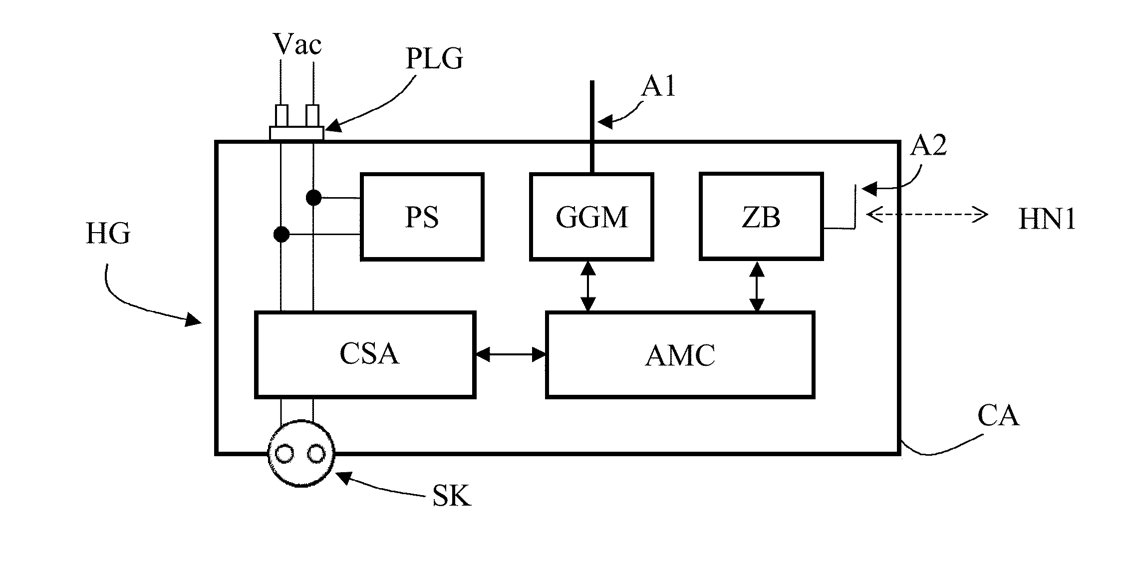
remote assistance and preventive servicing services regarding the abovementioned first electric appliance. The device according to the invention may be advantageously associated to the offer of extending the duration of the total guarantee of the considered electric appliance, represented for example by a household appliance. In such a manner, the electric appliance may send to the remote centre, day after day, information of statistical type regarding the use of the household appliance and, whenever required, also information of diagnostic type generated by the self-diagnosis system of the product in cases of malfunction or incipient failure. A second important advantage of the invention is the possibility to associate, to the same communication device which supplies the first electric appliance, also one or more further electrical appliances and / or other electrical devices connected to the same local area network to which the device object of the invention is connected. In such a manner, the same device may be exploited for connecting the further electrical appliances to the remote centre that offers remote assistance and preventive servicing services. A further advantage of the invention is the possibility to associate, to the same communication device that supplies the first electric appliance and dialogues with the possible further appliances or devices is connected to the abovementioned local network, possible sensor means present in the same household environment and also connected to the same local network.
[0037]Furthermore, due to the abovementioned characteristics, the communication device according to the invention is flexible to use, and it can be used advantageously in combination with electrical appliances capable of communicating only by means of the power supply cable thereof, in combination with electrical appliances capable of communicating only by means of a communication node (installed on board the same) of the local network, and in combination with electrical appliances not prearranged for communicating with the external environment.
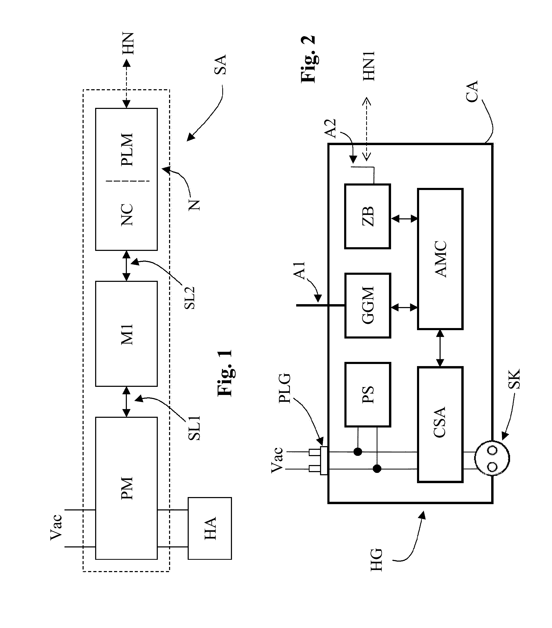
[0038]Furthermore, the Applicant observed that the functional accuracy and reliability of the device SA according to WO 02 / 21664 may be improved by configuring the microcontroller M1 in such a manner that the latter acquires from the power meter PM, during each mains period, a significant set of samples of the quantity representative of the electric energy consumed by the electric appliance HA within said mains period, and calculates its derived value (such as the average value, or the effective value, or the maximum value, or any other quantity obtained by suitably combining the values of the abovementioned significant set of samples). The same microcontroller M1 compares the derived value thus calculated with the abovementioned reference value, and then generates the high logic level depending on the result of the comparison. However, according to this approach, the power meter—in order to be able to supply to the microcontroller M1 all the information required for decoding the digital information sent by the electric appliance HA—must constantly and quickly exchange information with the microcontroller itself. On the other hand, the microcontroller M1 must acquire, within each mains period, a sufficiently high number (i.e. such to guarantee the efficiency of the measurement) of sampled values of the quantity representative of the electric energy consumed by the appliance HA in that same mains period, and it must constantly execute a quite complex software algorithm to perform the correct decoding of the possible digital information associated to the abovementioned network period. Thus, the microcontroller must be provided with a high processing power, and this has an impact on the overall cost of the monitoring device.
[0039]According to a second aspect, the present invention has the aim of providing a solution capable of overcoming these drawbacks. This aim is attained by an integrated measuring circuit and by a device for communicating and / or monitoring electrical appliances having the characteristics indicated in claims 23-44.
[0040]In summary, the abovementioned integrated circuit comprises means for measuring at least one quantity EJ representative of the electric energy absorbed from the electric mains, during a general mains period TJ, by an electric appliance. The circuit also integrates:
[0041]hardware means, i.e. made by means of logic circuits, to compare the value of the abovementioned quantity EJ with at least one reference value, and

Problems solved by technology

However, such a gateway is not yet available in the market at costs accessible for the larger share of consumers.

Method used


Image

  • Communication device for household electric appliances and monitoring system using said device
  • Communication device for household electric appliances and monitoring system using said device
  • Communication device for household electric appliances and monitoring system using said device

Examples


case c

[0129]In case c), assuming that the power socket SK of the device HG is connected to an electric appliance not provided with any means for communicating with the external environment (i.e. it is not provided with a communication node connected to the local network HN1 and it is not prearranged for communicating according to the general teachings of WO 02 / 21664), the same device HG is capable of periodically acquiring and sending to a remote service centre RMC information regarding the trend of the electric energy consumptions associated to said electric appliance over time.

[0130]FIG. 10 shows a second example of use of the invention, wherein now connected—respectively directly and indirectly—to the device HG, inserted into any standard power socket DS, is the household appliance HA2 and the household appliance HA1. In such case, referring to the electric appliance HA2, the device HG receives from said appliance statistical and diagnostic data through the local network HN1 and therei...


PUM


Abstract

A communication device, for connecting one or more electrical appliances to a remote service centre, comprises a control unit (AMC), means (PLG) for connecting the device (HG) to an alternating voltage electric mains network (Vac) and means (SK) for supplying the alternating mains voltage (Vac) to a power supply line of an electric appliance. The device (HG) further comprises first communication means (CSA), prearranged for receiving information possibly generated by the electric appliance and transmitted through the power supply line thereof, second communication means (ZB), prearranged for establishing a connection with a local area network (HN1) and third communication means (GGM), prearranged for establishing a connection with a further communication network, different from the local network (HN1), to which the remote service centre is connected. The control unit (AMC) is prearranged for acquiring by means of the first communication means (CSA), first information possibly generated by the electric appliance and transmitted through the power supply line thereof and/or second information regarding electric energy consumptions associated to the operation of is the electric appliance, acquiring, by means of the second communication means (ZB), third information possibly available on the local network (HN1), and transmitting to the remote centre (RMC), by means of the third communication means (GGM), at least one of the first, second and third information.

Description

BACKGROUND OF THE INVENTION[0001]1. Field of the Invention[0002]The present invention regards the subject of remote assistance and preventive servicing of electric appliances, particularly household electric appliances.[0003]2. Prior Art[0004]This subject was faced by the same Applicant in WO 99 / 43068. Such document describes a system for monitoring household appliances installed in the same household environment, whose control systems are prearranged for generating information of functional, diagnostic and statistical type, useful for technical servicing. The information generated by the household appliances is entered into a local area network, connected to which is a monitoring device, configured to gather the abovementioned information. The local network is represented by the same household is electric system, the communication system being of the power line communication type: for such purpose, the monitoring device and the household appliances of the system are provided with r...

Claims


Application Information

Patent Timeline
Patent Type & Authority Applications(United States)
IPC IPC(8): G06F19/00G01R21/00
CPCH04B3/54H04L12/2834H04L12/2825H04B2203/5454
Inventor AISA, VALERIOCONCETTONI, FABRIZIOCORRIAS, SILVIO
Owner WHIRLPOOL EMEA SPA
Why Eureka
Try Eureka