System and method for reducing power-on transient current magnitude

a technology of power-on transient current and system method, which is applied in the direction of logic circuits, pulse techniques, reliability increasing modifications, etc., can solve the problems of large transient current magnitude, damage to circuitry, and difficulty in providing power to circuitry in an integrated circuit, so as to achieve uniform distribution throughout the integrated circuit and shorten the turn-on time

Active Publication Date: 2006-11-28
TEXAS INSTR INC
View PDF3 Cites 30 Cited by
  • Summary
  • Abstract
  • Description
  • Claims
  • Application Information

AI Technical Summary

Benefits of technology

[0012]An advantage of a preferred embodiment of the present invention is that a large number of small switches can operate in conjunction to spread out the power-up sequence over an extended period of time.
[0013]A further advantage of a preferred embodiment of the present invention is that the use of a large number of small switches can result in the distribution of the switches (current sources) over a wider area of the integrated circuit. This can result in a power-up that is more evenly distributed throughout the integrated circuit.
[0014]Yet another advantage of a preferred embodiment of the present invention is that the use of the large number of small switches can result in a shorter turn-on time since a delay associated with each small switch can be significantly smaller than a delay associated with a larger switch.

Problems solved by technology

Providing power to circuitry in an integrated circuit can be a difficult proposition, especially during power-on (turn on) and power-off (turn off).
However, with a small internal resistance, when the integrated header switch is initially turned on to couple the power supply to the circuitry, a transient current with a large magnitude can result.
Damage to the circuitry can result if the magnitude of the transient current is too large.
Additionally, with a delay between consecutive switches being turned on, the transient current is spread out over time.
One disadvantage of the prior art is that even with smaller transistors being used in the distributed header switches, as each switch is being turned on, a transient current of significant magnitude can still occur.
A second disadvantage of the prior art is that since each of the transient currents produced when a smaller switch is turned on may still exceed the normal operating current, each one of the smaller switches can be replaced with multiple switches that are even smaller.
However, due to the delay between turning on consecutive switches, the total amount of time required to provide power to the circuitry can be very long.
Another disadvantage of the prior art is that the use of switches with slow gate transitions is that the design of these switches is essentially an analog design task.
This does not scale well to a digital design environment with automatic cell routing and placement, making the design of the integrated header switch more difficult and expensive.
Furthermore, changes to the design of the integrated header switch can take longer and may require a substantial re-design of the integrated header switch.

Method used


Image

  • System and method for reducing power-on transient current magnitude
  • System and method for reducing power-on transient current magnitude
  • System and method for reducing power-on transient current magnitude

Examples


Embodiment Construction

[0026]The making and using of the presently preferred embodiments are discussed in detail below. It should be appreciated, however, that the present invention provides many applicable inventive concepts that can be embodied in a wide variety of specific contexts. The specific embodiments discussed are merely illustrative of specific ways to make and use the invention, and do not limit the scope of the invention.

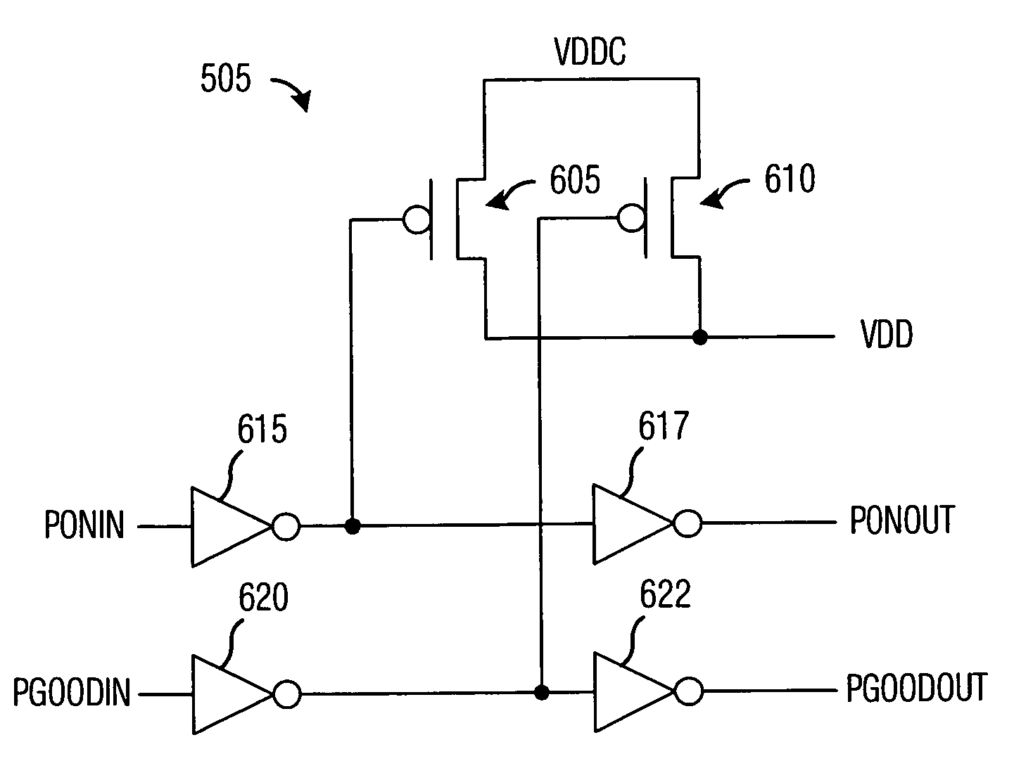
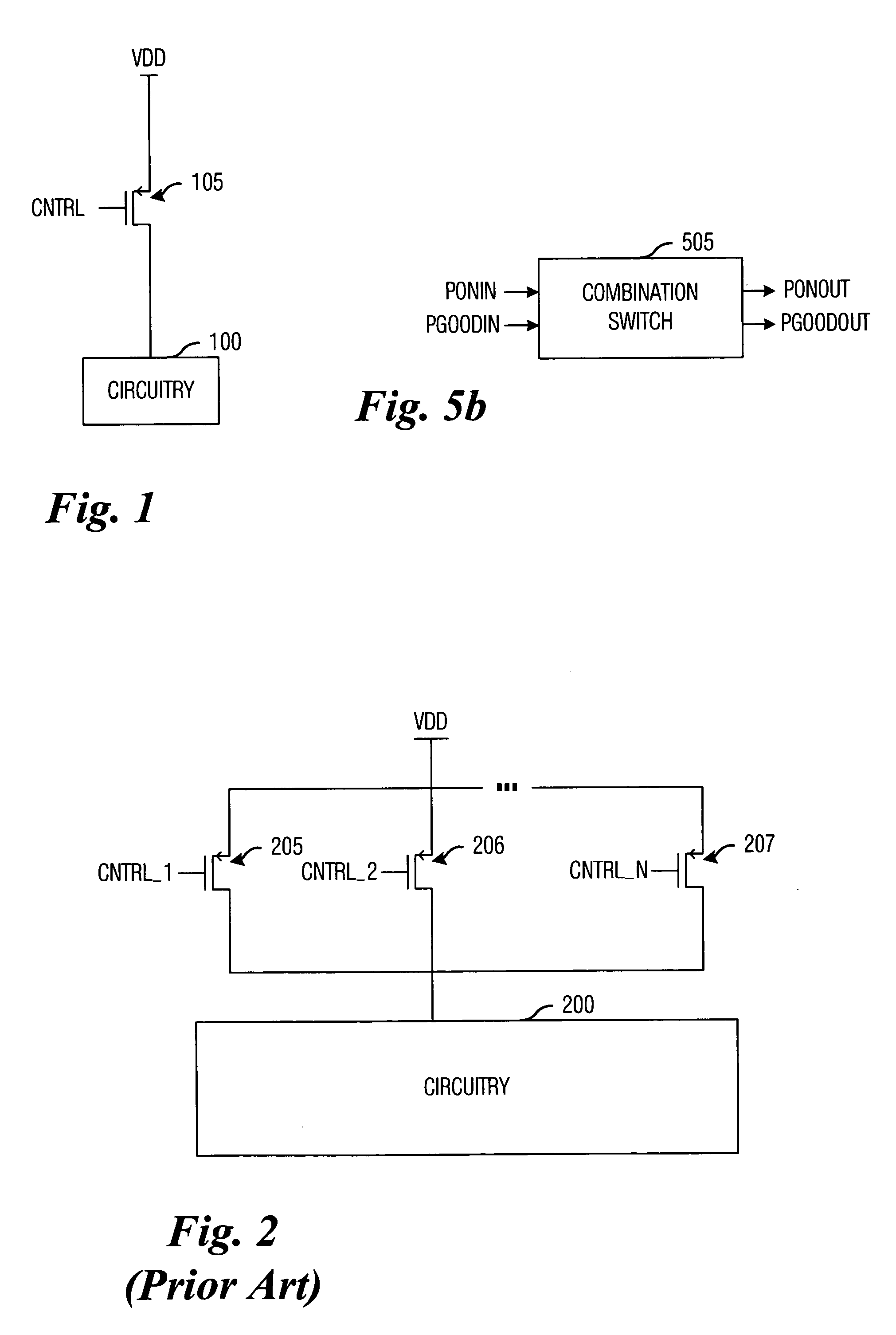
[0027]The present invention will be described with respect to preferred embodiments in a specific context, namely a distributed header switch for providing power to logic circuitry in an integrated circuit, such as in a system-on-a-chip (SOC) application, wherein there is a need to provide power to different regions of the integrated circuit with potentially different power requirements at the different regions. The invention may also be applied, however, to other power supply applications, wherein there is an interest in reducing power-on transient currents and minimizing po...


PUM


Abstract

System and method for reducing power-on transient current magnitude on distributed header switches. A preferred embodiment comprises a distributed header switch coupling a circuit to a power supply, the distributed header switch comprising a linear sequence of combination switches, each combination switches containing a pre-charge switch and a header switch. A first-pass involves sequentially turning on each of the pre-charge switches, which enables a voltage level at the distributed header switch to approach that of a final voltage level and a second-pass involves sequentially turning on each of the header switches. Since the voltage level at the distributed header switches is close to the final voltage level, a resulting transient current is small in magnitude.

Description

TECHNICAL FIELD[0001]The present invention relates generally to a system and method for integrated circuits, and more particularly to a system and method for reducing power-on transient current magnitude on distributed header switches.BACKGROUND[0002]Providing power to circuitry in an integrated circuit can be a difficult proposition, especially during power-on (turn on) and power-off (turn off). An integrated header switch is typically used to couple a power supply to the circuitry. To minimize voltage drop across the integrated header switch, the integrated header switch's internal resistance is minimized. However, with a small internal resistance, when the integrated header switch is initially turned on to couple the power supply to the circuitry, a transient current with a large magnitude can result. Damage to the circuitry can result if the magnitude of the transient current is too large. Furthermore, to help ensure chip-level reliability, it is important to ensure that the max...

Claims


Application Information

Patent Timeline
Patent Type & Authority Patents(United States)
IPC IPC(8): H03K19/096
CPCH03K17/164
Inventor MAIR, HUGH T.LAGERQUIST, ROLF
Owner TEXAS INSTR INC
Why Eureka
Try Eureka