Last leg power grid high-speed data transmitter and receiver structures
Inactive Publication Date: 2006-11-28
CURRENT GRID
View PDF4 Cites 106 Cited by
Summary
Abstract
Description
Claims
Application Information
AI Technical Summary
This helps you quickly interpret patents by identifying the three key elements:
Problems solved by technology
Method used
Benefits of technology
Benefits of technology
[0019]Another transmitter/receiver component of the present invention that improves system performance is an echo cancellation and adaptive equalization function. The echo cancellation and adaptive equalization function serves to precondition transmitted signals and to equalize received signals to overcome the frequency dependent characteristics of the power grid that carries the high data rate communication signals. In particular, the input impedance of the power grid (at the coupling point of a transceiver) is characterized across an operating frequency band. This characterized input impedance is used by the transmitter to adjust the
Problems solved by technology
As is also known, the last hundred feet of a communication system, i.e., the connection to each individual user, is the most costly and most difficult to install.
In addition, many homes are very difficult to physically access, making the installation of the local connection even more difficult and more costly.
The power companies
Method used
Image
Click on the blue label to locate the original text in one second.
Reading with bidirectional positioning of images and text.
Examples
Example
DETAILED DESCRIPTION OF THE FIGURES
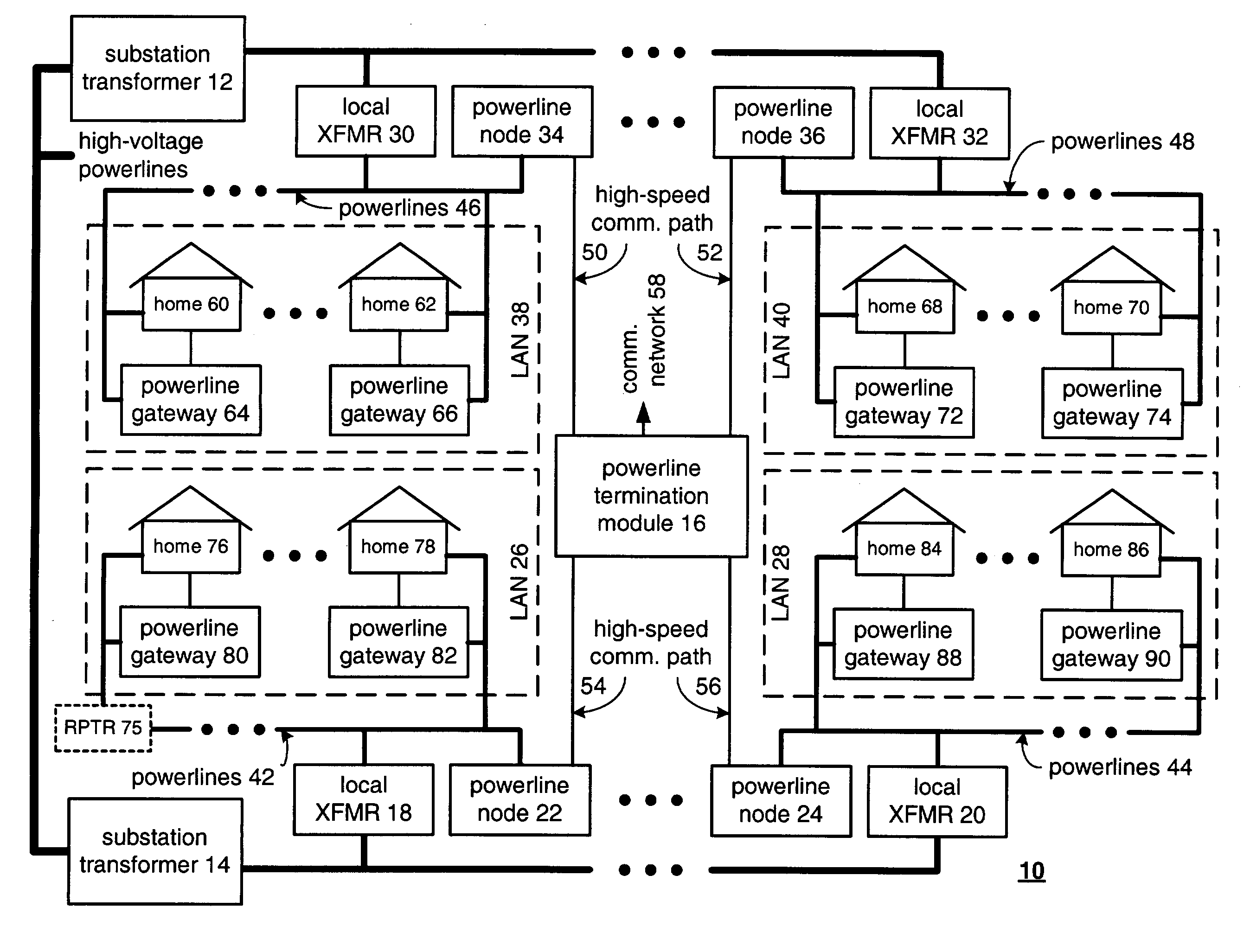
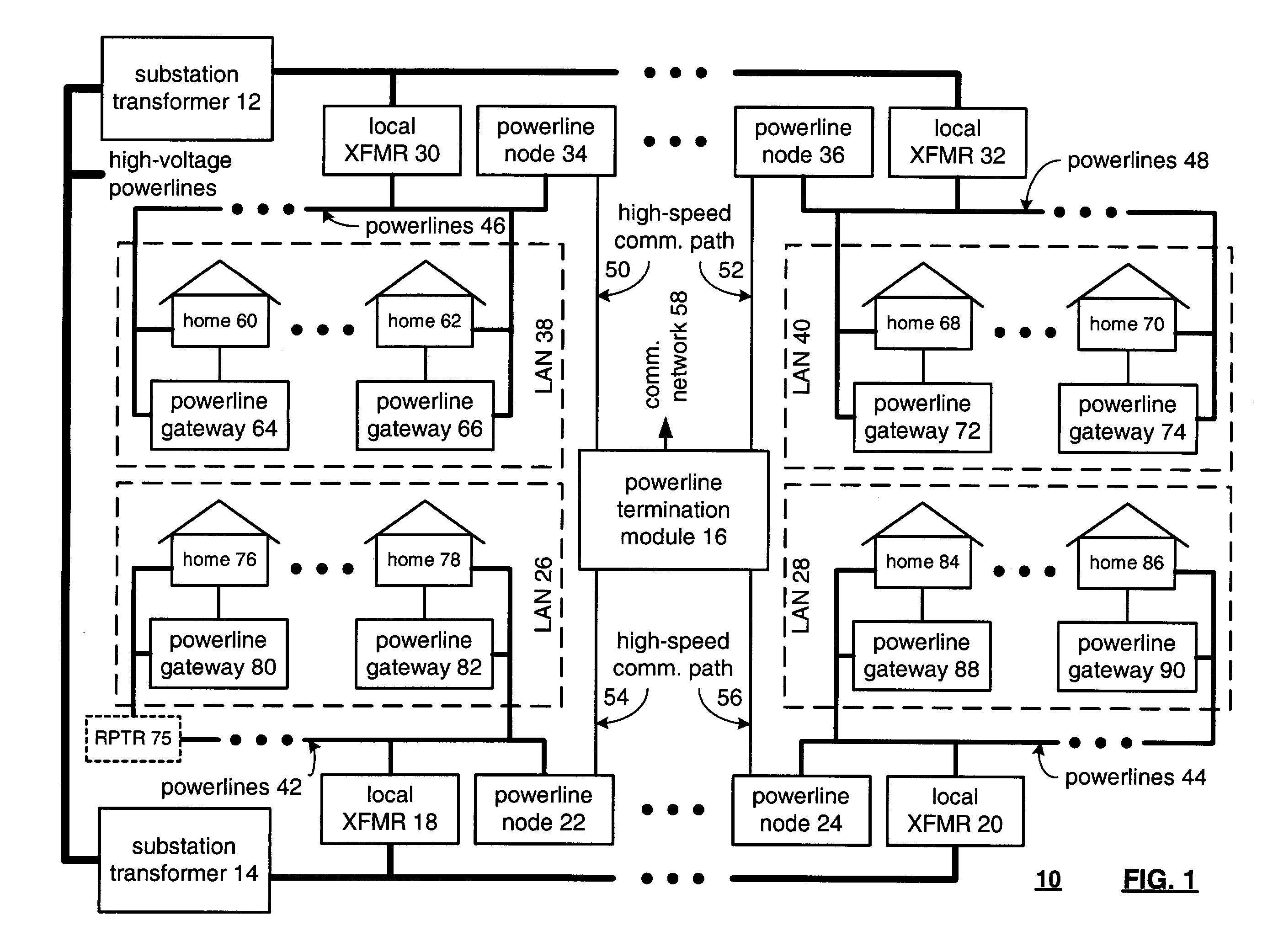
[0049]FIG. 1 illustrates a schematic block diagram of a powerline based communication system 10. The system 10 includes a plurality of substation transformers 12 and 14, a plurality of local transformers 30, 32, 18, and 20, a plurality of powerline nodes 34, 36, 22, and 24, a plurality of local area networks 26, 28, 38, and 40, and a powerline termination module 16. As one of average skill in the art will appreciate, more or less substation transformers, local transformers, powerline nodes, powerline termination modules, and local area networks may be included in a communication system that provides similar communication services as that of the powerline base communication system 10. Accordingly, the elements illustrated, and the quantities thereof, are in no way to be construed as to limit the number of elements that may be included in the communication system 10 but are shown to illustrate the concepts of the present invention. The same applies t...
PUM
Abstract
A powerline based communication system includes a powerline termination module, a plurality of powerline gateways, and a plurality of powerline nodes. The powerline termination module manages data for local area networks within the powerline based communication system. The plurality of powerline gateways is arranged in sets of powerline gateways, wherein each set of powerline gateways constitutes a local area network. Each of the plurality of powerline nodes is operably coupled to the powerline termination module via a high-speed communication path. In addition, each powerline node is operably coupled to set of powerline gateways, i.e., to a local area network, via powerlines of a local transformer. Each of the powerline nodes receives data for its respective LAN from the powerline termination module and provides the data to the powerline gateways of its LAN via the powerlines of the local transformer.
Description
CROSS REFERENCES TO RELATED APPLICATIONS[0001]This application claims priority to U.S. Provisional Application Ser. No. 60 / 358,251, filed Feb. 20, 2002, U.S. Regular application Ser. No. 09 / 860,260, filed May 18, 2001, U.S. Regular application Ser. No. 09 / 860,261, filed May 18, 2001, U.S. Regular application Ser. No. 09 / 860,262, filed May 18, 2001, and U.S. Regular application Ser. No. 09 / 860,263, filed May 18, 2001, all of which are incorporated herein by reference.BACKGROUND OF THE INVENTION[0002]1. Technical Field of the Invention[0003]The present invention relates generally to communication systems; and more particularly to high data rate communication systems being partially serviced across a power grid.[0004]2. Related Art[0005]As is known, data may be communicated from one entity (e.g., end user's computer, server, facsimile machine, web browser, et cetera) to another entity via a communication infrastructure. The communication infrastructure may include a public switched tel...
Claims
Application Information
Patent Timeline
Application Date:The date an application was filed.
Publication Date:The date a patent or application was officially published.
First Publication Date:The earliest publication date of a patent with the same application number.
Issue Date:Publication date of the patent grant document.
PCT Entry Date:The Entry date of PCT National Phase.
Estimated Expiry Date:The statutory expiry date of a patent right according to the Patent Law, and it is the longest term of protection that the patent right can achieve without the termination of the patent right due to other reasons(Term extension factor has been taken into account ).
Invalid Date:Actual expiry date is based on effective date or publication date of legal transaction data of invalid patent.

