Swiped aperture capacitive fingerprint sensing systems and methods

a capacitive fingerprint and aperture technology, applied in the field of capacitive fingerprint sensing systems and methods, can solve problems such as difficulty in achieving, number of transistor devices, and breakdown, and achieve the effect of faster ra

Inactive Publication Date: 2006-12-05
SYNAPTICS INC
View PDF53 Cites 136 Cited by
  • Summary
  • Abstract
  • Description
  • Claims
  • Application Information

AI Technical Summary

Problems solved by technology

This approach, however, requires extraordinary resiliency and durability in the polymer insulating film, which is difficult to achieve.
First is the large number of transistor devices that are required to scan and measure the more than ten thousand capacitors in such an array at a 100 micron pitch.
Second is the problem of electrostatic discharge from a charged human body through the finger, breaking down the thin insulator that separates the finger from the sensitive electrodes and destroying the low voltage transistors that operate the array.
A third problem is the risk of mechanical damage that is posed by direct physical contact of the finger to an exposed silicon die.
All of the known prior art electronic fingerprint sensing systems have had one or more disadvantages, including low reliability and high cost.

Method used


Image

  • Swiped aperture capacitive fingerprint sensing systems and methods
  • Swiped aperture capacitive fingerprint sensing systems and methods
  • Swiped aperture capacitive fingerprint sensing systems and methods

Examples


second embodiment

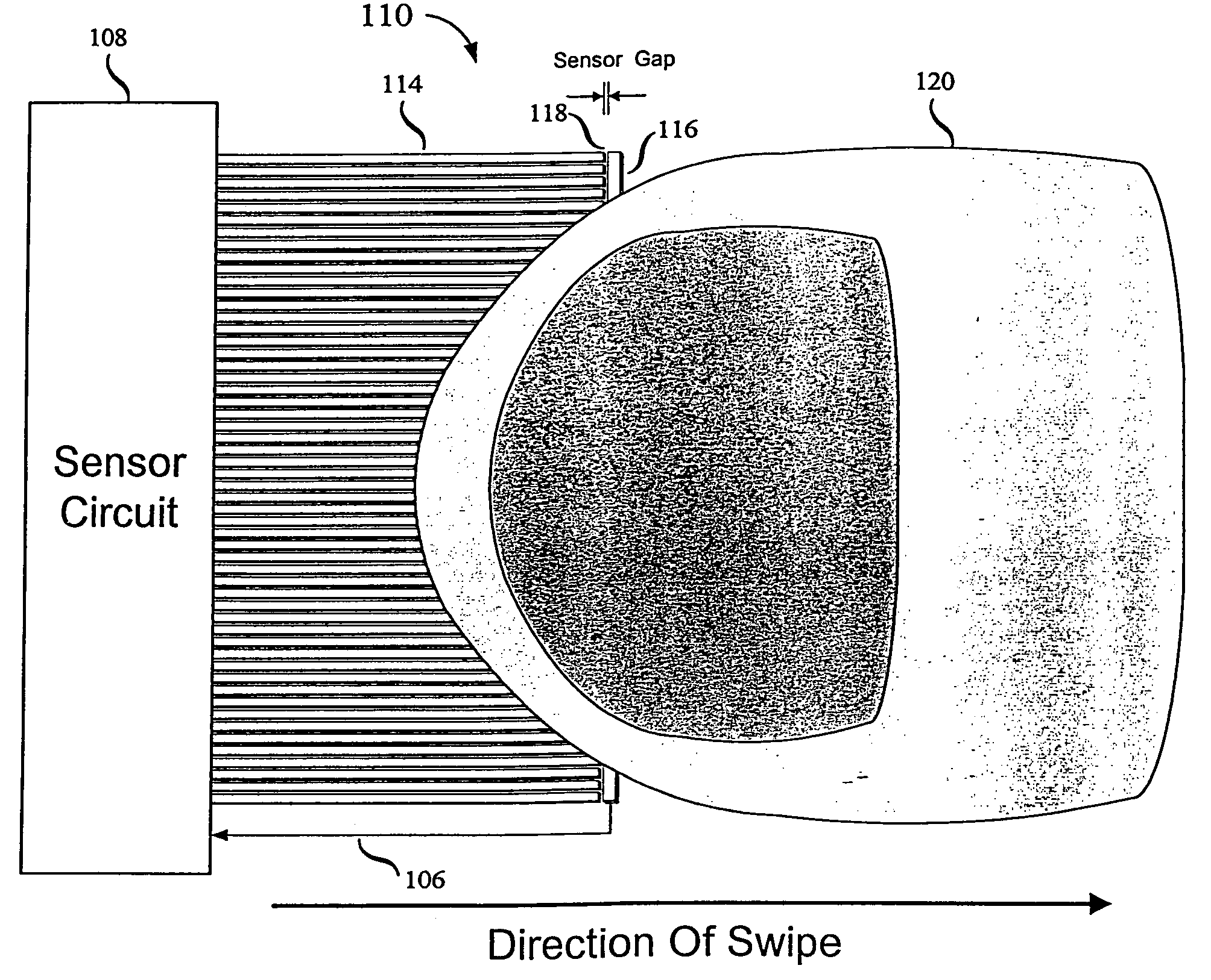
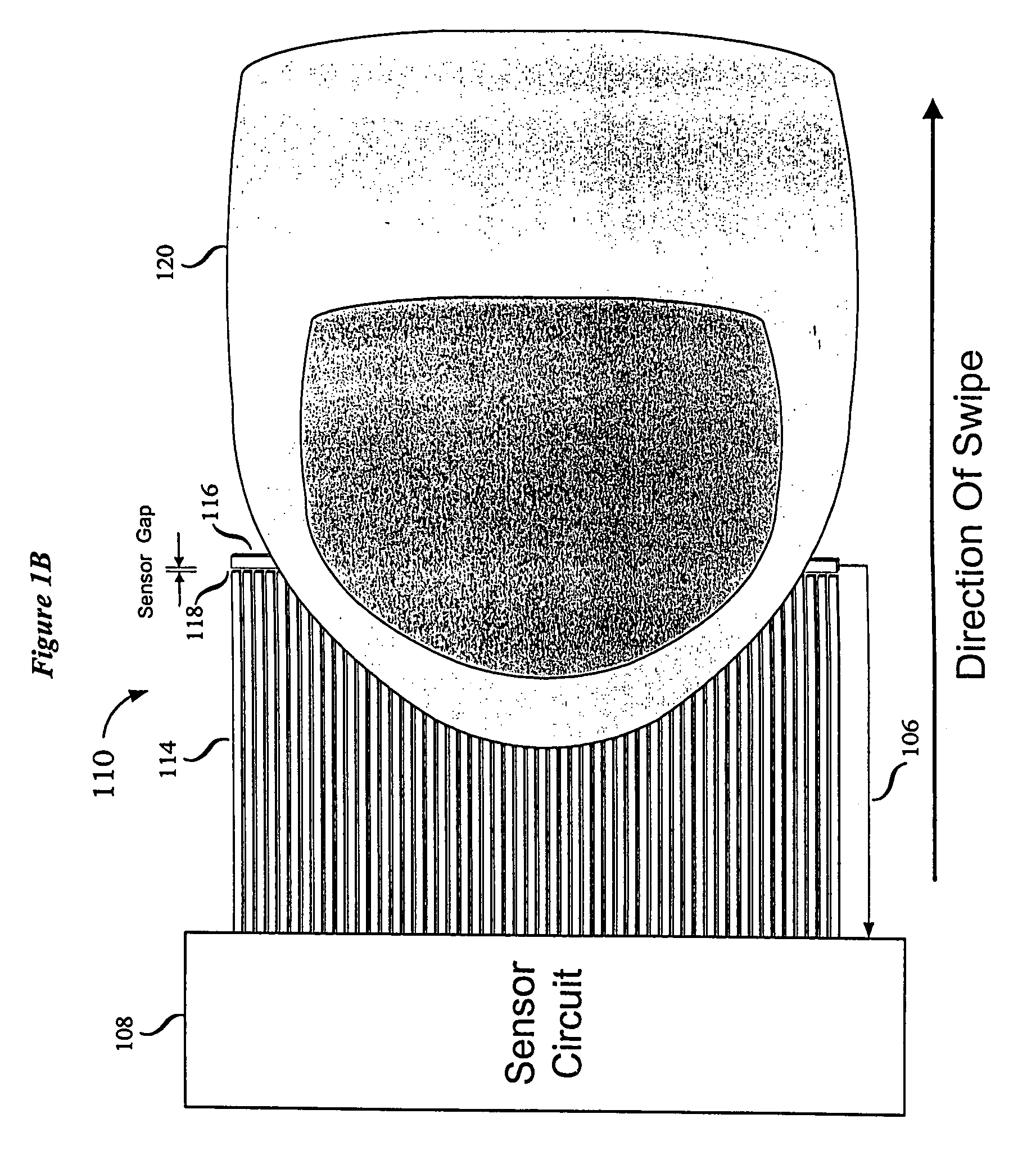
[0092]rate sensor 112 is shown in FIG. 10. In this embodiment, the orientation of image sensor 110 is reversed with respect to the direction of finger swipe. Rate sensor 112 is located on the opposite side of image sensor pickup plate 116 from drive plates 114. This configuration permits the rate drive plates and rate pickup plates to extend across the entire width of the sensor, thereby providing larger sensed signals. As shown in FIG. 10, rate sensor 112 includes finger detectors 1010, 1012, 1014 and 1016 spaced apart along the direction of finger swipe by a spacing 1006. Each of the finger detectors includes at least one rate drive plate and one rate pickup plate. Thus, for example, finger detector 1010 includes rate drive plate 1010a and rate pickup plate 1010b. The rate pickup plates of each of the finger detectors 1010, 1012, 1014 and 1016 are connected to the pickup plate 116 of image sensor 110. In other embodiments, the rate pickup plate and the image pickup plate can be el...

third embodiment

[0093]rate sensor 112 is shown in FIG. 11. The embodiment of FIG. 11 uses differential rate sensing. Rate sensor 112 includes finger detectors 1120, 1122, . . . 1130 positioned along the direction of finger swipe. Each of the finger detectors has a differential configuration. In particular, each finger detector includes a drive plate and first and second pickup plates located on opposite sides of the drive plate. For example, finger detector 1120 includes a drive plate 1140 and pickup plates 1142 and 1144 located on opposite sides of drive plate 1140. Pickup plate 1142 is spaced from drive plate 1140 by sensor gap 1150, and pickup plate 1144 is spaced from drive plate 1140 by sensor gap 1152. Drive plate 1140 and pickup plates 1142 and 1144 may be elongated conductors oriented perpendicular to the direction of finger swipe across the image sensor 110. In the embodiment of FIG. 11, drive plate 1140 is wider than pickup plates 1142 and 1144 and is connected to a drive circuit via a co...


PUM


Abstract

A fingerprint sensing system includes an image sensor, a rate sensor and a sensor circuit. The image sensor includes a linear array of capacitive sensors for capacitive sensing of ridge peaks and ridge valleys of a fingerprint on a swiped finger. The rate sensor senses the speed of the finger as it is swiped across the image sensor. The sensor circuit supplies image drive signals to the image sensor and detects image signals in response to the drive signals. The sensor circuit supplies rate drive signals to the rate sensor and detects rate signals in response to the rate drive signals. The sensor circuit further coordinates the image signals and the rate signals to provide a fingerprint image. The image sensor may be configured as an image pickup plate and multiple image drive plates formed on a substrate, such as a flexible printed circuit board or other flexible substrate which may conform to the shape of the finger.

Description

CROSS REFERENCE TO RELATED APPLICATIONS[0001]This application is a division of U.S. application Ser. No. 10 / 005,643, filed Dec. 5, 2001, which claims the benefit of provisional application Ser. No. 60 / 251,371, filed Dec. 5, 2000, and which is hereby incorporated by reference.FIELD OF THE INVENTION[0002]This invention relates to systems and methods for electronically sensing topographic features of an object, such as a fingerprint. More particularly, the invention relates to systems and methods for capacitive sensing of a fingerprint on a swiped finger.BACKGROUND OF THE INVENTION[0003]Electronic fingerprint sensing has received increased attention as a technique for reliable identification of individuals. Electronic fingerprint sensing may be used in stationary equipment, such as security checkpoints, or in portable devices, such as mobile phones and other wireless devices, and smart cards. Accordingly, electronic fingerprint sensing systems are required to be compact, highly reliabl...

Claims


Application Information

Patent Timeline
Patent Type & Authority Patents(United States)
IPC IPC(8): G06K9/00
CPCG06K9/0002G06K9/00026G06V40/1335G06V40/1306
Inventor BENKLEY, III, FRED G.
Owner SYNAPTICS INC
Why Eureka
Try Eureka