Surgical stapling instrument having an electroactive polymer actuated buttress deployment mechanism

a technology of electroactive polymer and deployment mechanism, which is applied in the direction of surgical staples, paper/cardboard containers, manufacturing tools, etc., can solve the problems of air leakage in the stapled lung tissue, the staple hole itself is easily damaged, and the instruments used in such procedures are typically long and narrow

Active Publication Date: 2006-12-12
CILAG GMBH INT
View PDF35 Cites 2717 Cited by
  • Summary
  • Abstract
  • Description
  • Claims
  • Application Information

AI Technical Summary

Problems solved by technology

Moreover, laparoscopic and endoscopic procedures often require the surgeon to act on organs, tissues and / or vessels far removed from the incision.
Thus, instruments used in such procedures are typically long and narrow while being functionally controllable from the proximal end of the instrument.
One known problem with using surgical staplers in this fashion has been the formation of air leaks in stapled lung tissue.
The leaks can occur in the cut line, and / or in the staple holes themselves.
Frequently, the diseased lung tissue is thin and friable and can tear at the staples as the lungs re-inflate.
These air leaks can be persistent and can extend the hospital stay for a patient by weeks.
Releasably attaching the buttress material to the jaw members of the surgical stapling device presents a special challenge.
However, the portions of the buttress material having the adhesive applied thereto are not releasable from the device.
As a consequence, removing the buttress from the instrument (after firing) can be especially difficult, as all of the material between the perforations must be torn simultaneously to release the surgical stapling device from tissue.
While sleeves can effectively be used to attach the buttress material to the end effector of the surgical stapling device, sleeves can cause other complications during surgery.

Method used


Image

  • Surgical stapling instrument having an electroactive polymer actuated buttress deployment mechanism
  • Surgical stapling instrument having an electroactive polymer actuated buttress deployment mechanism
  • Surgical stapling instrument having an electroactive polymer actuated buttress deployment mechanism

Examples


Embodiment Construction

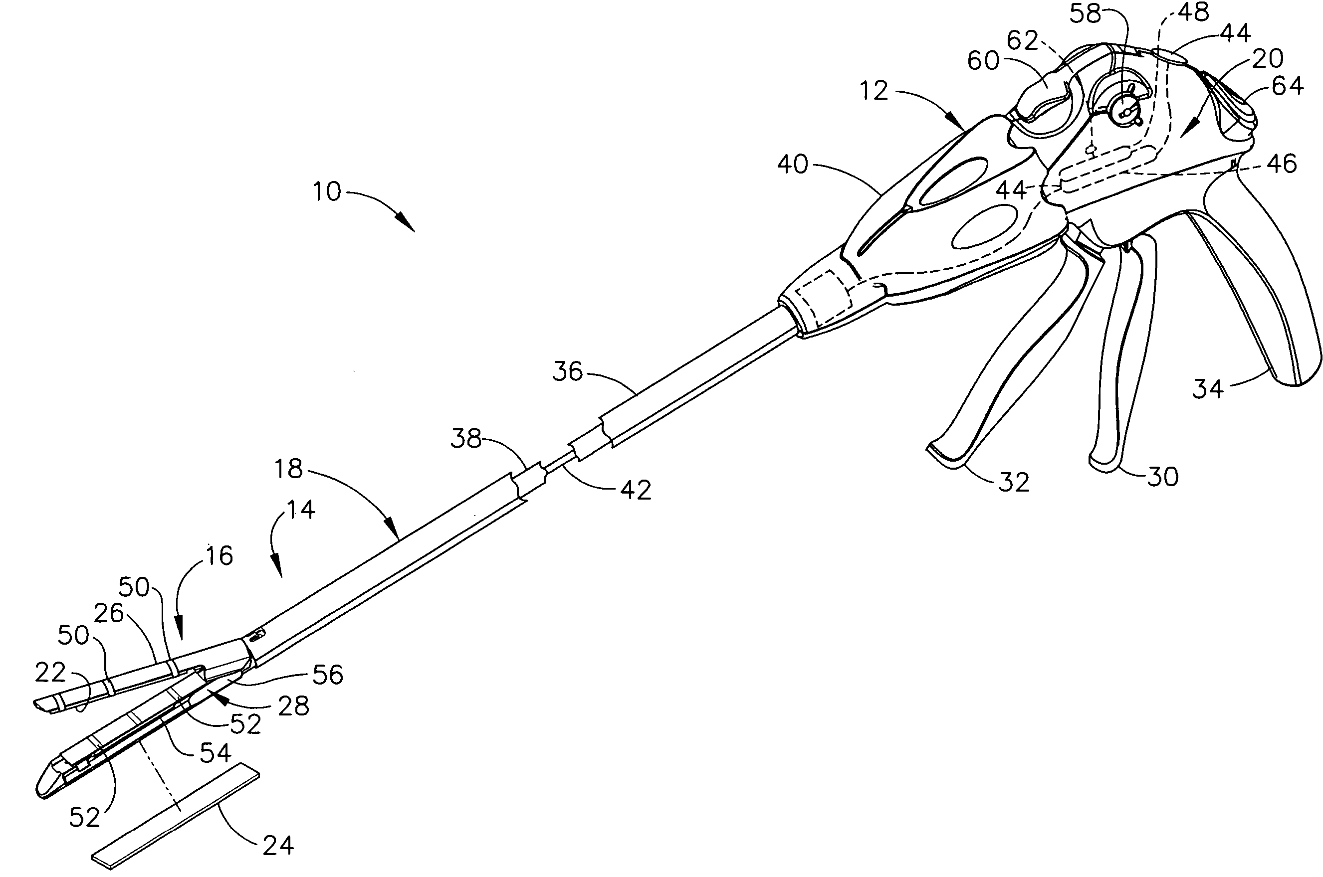
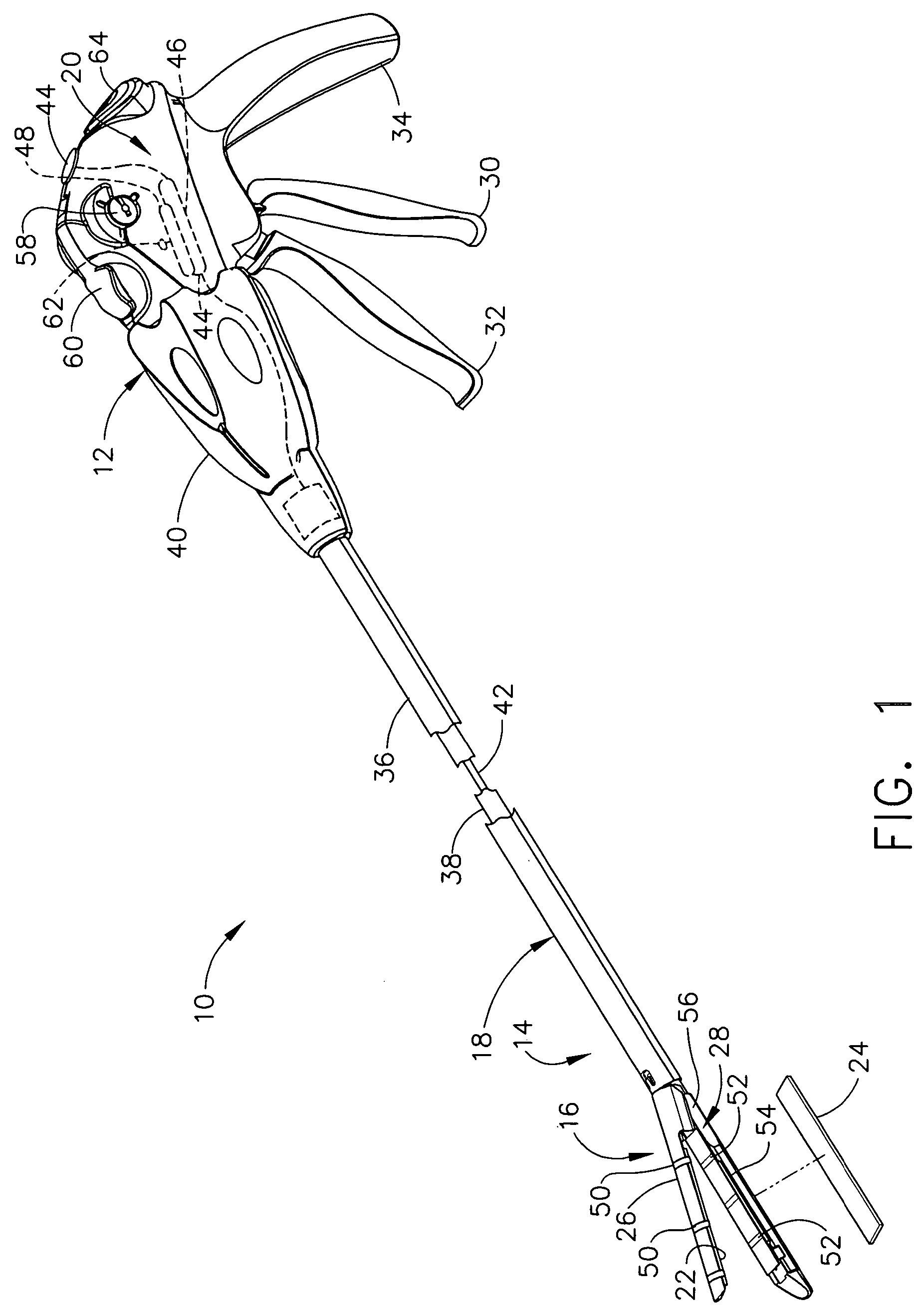
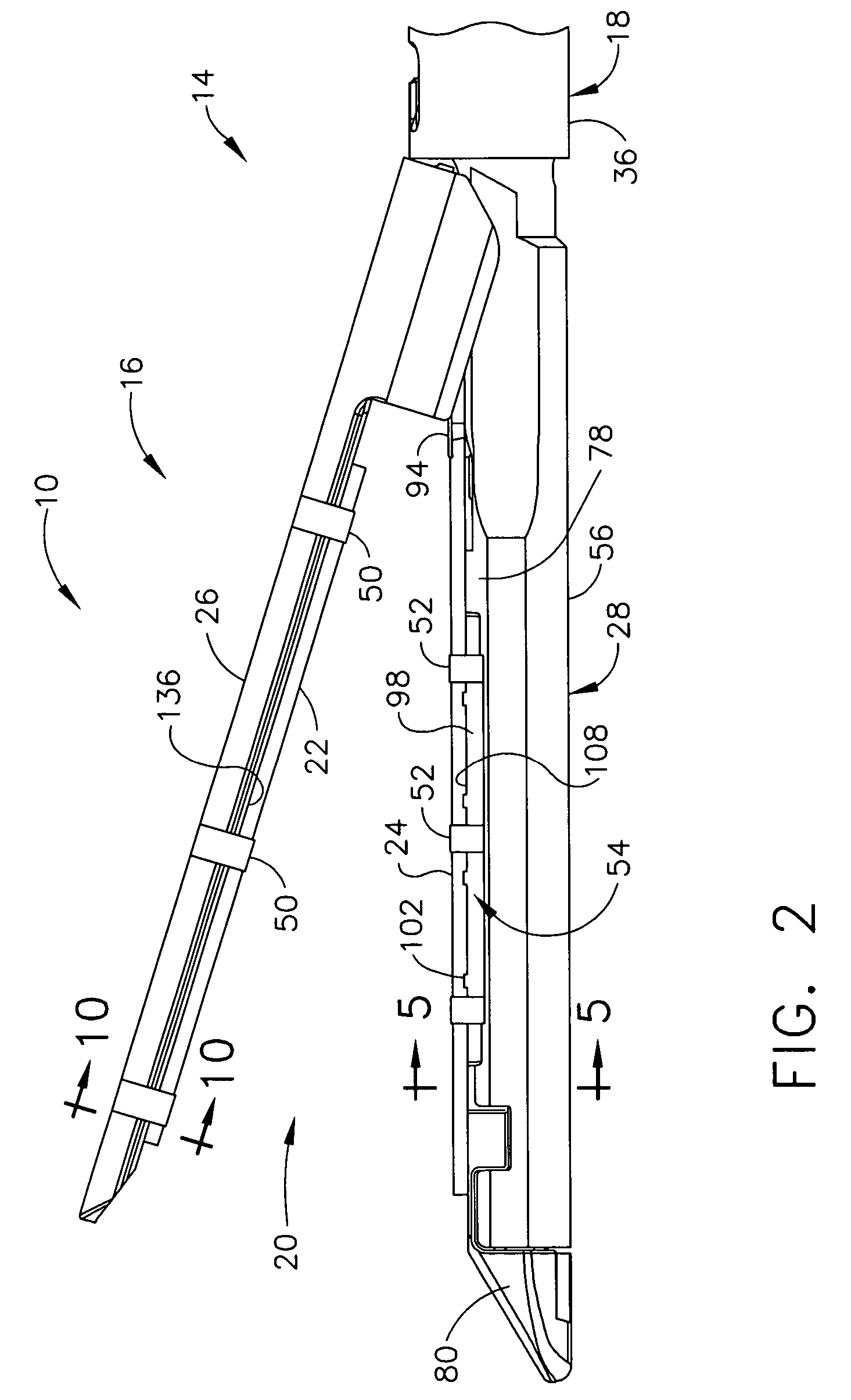
[0041]Turning to the Drawings, wherein like numerals denote like components throughout the several views, in FIGS. 1–2, a surgical stapling and severing instrument 10 includes a handle portion 12 that manipulates to position an implement portion 14 formed from a fastening end effector, specifically a staple applying assembly 16, distally attached to an elongate shaft 18. The implement portion 14 is sized for insertion through a cannula of a trocar (not shown) for an endoscopic or laparoscopic surgical procedure. Advantageously, an electrically actuated buttress deployment mechanism 20 reliability retains upper and lower buttress pads 22, 24 respectively on an upper jaw (anvil) 26 and a lower jaw 28 until tissue clamped within the staple applying assembly 16 is stapled and severed. Thereafter, the electrically actuated buttress deployment mechanism 20 deploys the buttress pads 22, 24 without undue force or ancillary surgical procedures (e.g., use of a grasper).

[0042]The surgical stap...


PUM

PropertyMeasurementUnit
voltage potentialaaaaaaaaaa
electricallyaaaaaaaaaa
locking forceaaaaaaaaaa

Abstract

A surgical instrument for being endoscopically or laparoscopically inserted to a surgical site for simultaneous stapling and severing of tissue includes electrically actuated deployment of buttress pads held on inner surfaces of upper and lower jaws of a staple applying assembly. Thereby, thick or thin layers may be stapled and severed without improper staple formation nor with nonoptimal deployment of the buttress pads. Electroactive polymer (EAP) actuated latches, an EAP channel, or a rigid channel with an EAP pinch lock reliably hold the buttress pad until deployment is desired with a low force to separate the stapled and severed buttress pad / tissue combination with the respective EAP mechanism activated for deployment.

Description

CROSS REFERENCE TO RELATED APPLICATIONS[0001]This application claims the benefit of U.S. provisional application Ser. No. 60 / 591,694, entitled “SURGICAL INSTRUMENT INCORPORATING AN ELECTRICALLY ACTUATED ARTICULATION MECHANISM” to Shelton IV, filed 28 Jul. 2004.FIELD OF THE INVENTION[0002]The present invention relates in general to surgical stapler instruments that are capable of applying lines of staples to tissue while cutting the tissue between those staple lines and, more particularly, to improvements relating to stapler instruments and improvements in processes for forming various components of such stapler instruments including adding bolstering material to the severed and stapled tissue.BACKGROUND OF THE INVENTION[0003]Endoscopic and laparoscopic surgical instruments are often preferred over traditional open surgical devices since a smaller incision tends to reduce the post-operative recovery time and complications. The use of laparoscopic and endoscopic surgical procedures ha...

Claims


Application Information

Patent Timeline
Patent Type & Authority Patents(United States)
IPC IPC(8): A61B17/00
CPCA61B17/07207A61B17/07292A61B17/115A61B2017/00871A61B2017/07214A61B17/072A61B17/068A61B17/00
Inventor SHELTON, IV, FREDERICK E.
Owner CILAG GMBH INT
Why Eureka
Try Eureka