Printer paper tray

a paper tray and paper plate technology, applied in the field of paper plates, can solve the problems of high cost, paper not being picked, set of check procedures may not be regarded as user-friendly or robust,

Inactive Publication Date: 2006-12-12
HEWLETT PACKARD DEV CO LP
View PDF5 Cites 14 Cited by
  • Summary
  • Abstract
  • Description
  • Claims
  • Application Information

AI Technical Summary

Problems solved by technology

Additionally, high cost may be incurred both from the high number of parts and from the assembly of these complicated mechanisms.
Failure to do so may result in paper not being picked.
Such a set of check procedures may not be regarded as user-friendly or robust.
Within repair centers, failure of mechanisms to elevate paper for pick results in repairs (or even replacement) of the printer or the tray or both, which is a very costly solution.
In addition, trouble-shooting for the root cause of such a picking problem can be time consuming and tedious.

Method used


Image

  • Printer paper tray
  • Printer paper tray
  • Printer paper tray

Examples


Embodiment Construction

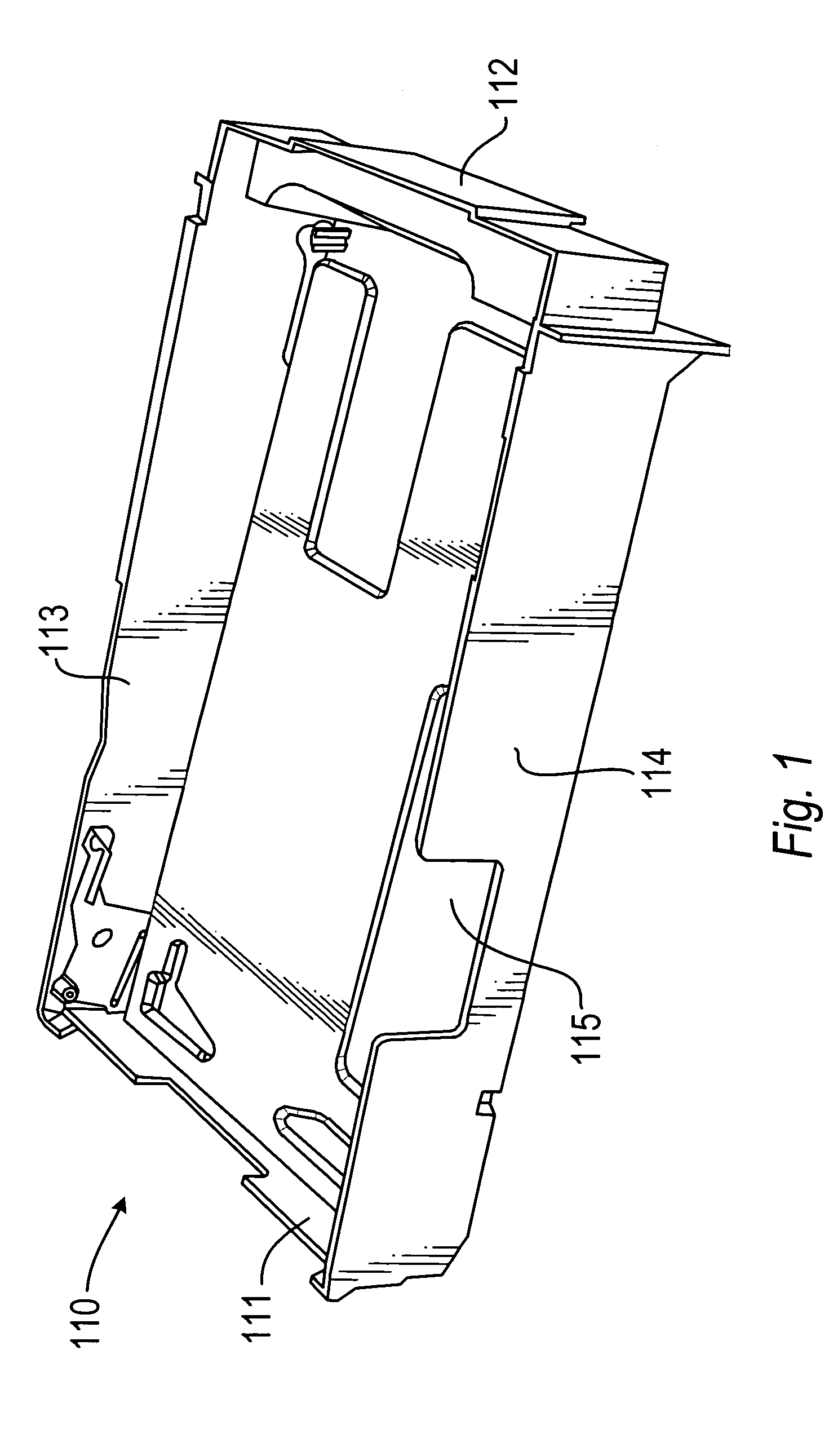
[0016]FIG. 1 shows a paper tray 110 for use with a front-loading printer, according to embodiments of the present invention. The tray 110 has a front end 111, which is designed to be inserted into a printer first, and a rear end 112, at the other end of the tray 110. The tray 110 also has first and second sides 113, 114, between the front and rear ends 111, 112 on each side of the tray 110, and a base 115, from which the sides 113, 114 and ends 111, 112 extend upwardly when the base 115 is placed horizontal.

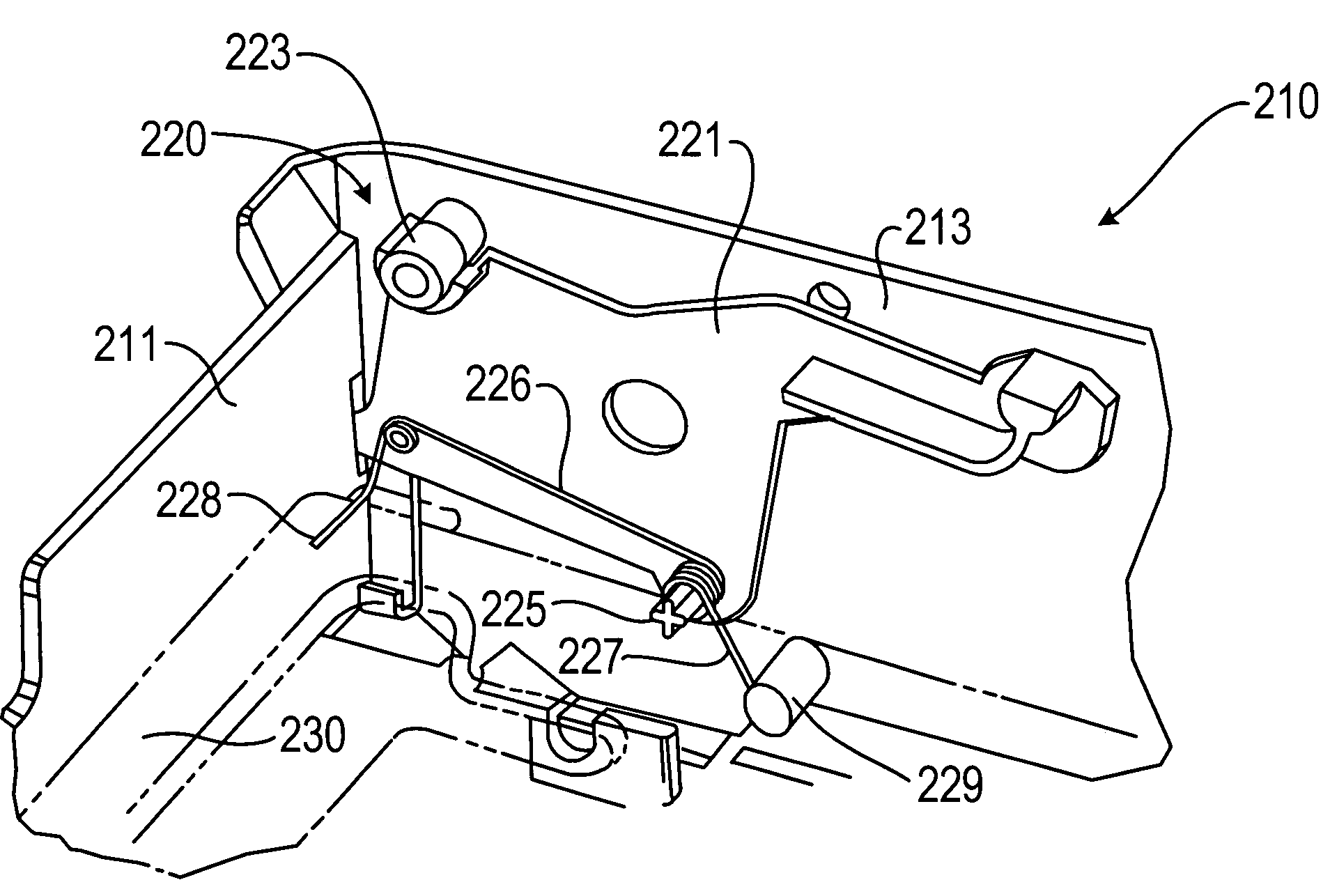
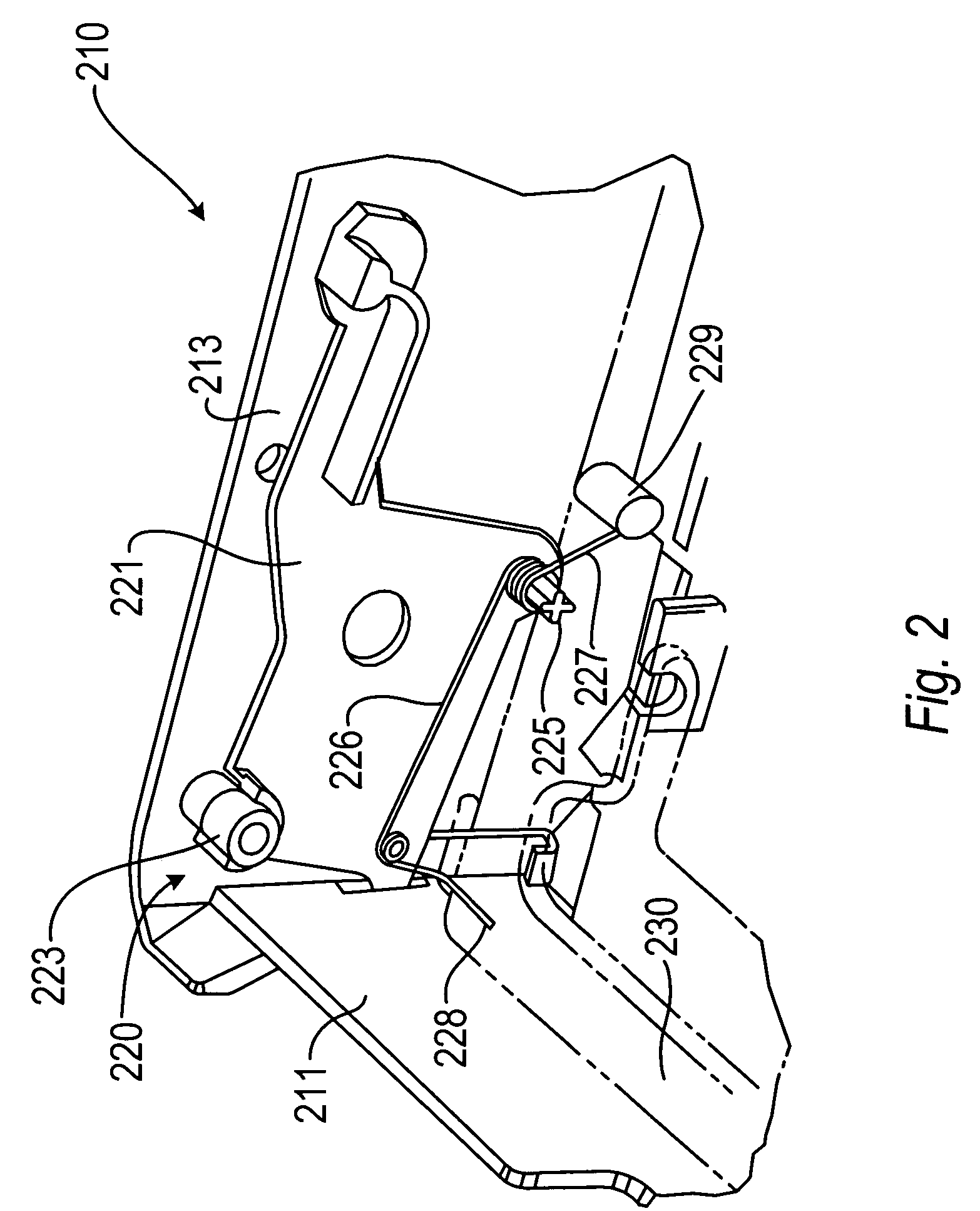
[0017]As shown in FIG. 2, a mechanism 220 according to an embodiment of the invention is mounted within a tray 210. The mechanism 220 includes an actuator 221 pivotably connected to the first side 213 of the tray 210 adjacent to the front end 211. In this embodiment, the mechanism includes another actuator, provided on the second side of the tray. In this embodiment, each actuator is a mirror image of the other in a plane parallel to the first and second sides 213, (not shown). T...


PUM


Abstract

A paper tray (110, 210, 310, 410, 510, 610, 710, 810) for holding a stack of sheets of paper in a printer (540, 640, 740, 840) is provided. The paper tray includes an actuator (221, 421, 521, 621, 721, 821), which is moveable between an engaged position by insertion of the tray into the printer and a refilling position by at least partial removal of the tray from the printer. A paper supporting plate (230, 330, 430, 530, 630, 730, 830) is moveably coupled to the actuator. The paper supporting plate supports the stack of paper so that a sheet furthest away from the paper supporting plate is in a picking position available for picking by the printer, when the actuator is in the engaged position. The actuator is coupled to the paper supporting plate so as to move the paper supporting plate away from the picking position when the actuator is moved into the refilling position.

Description

FIELD OF THE INVENTION[0001]The present invention relates to paper trays for storing paper to be used in printing. In particular, the present invention relates to trays having mechanisms for supplying paper to a printer.BACKGROUND OF THE INVENTION[0002]Inkjet, deskjet and laserjet printers have a paper tray to store a paper stack for printing. From this tray, stored paper is positioned for picking (removal from the paper stack) and then transported for printing.[0003]The paper in a paper tray is generally moved into a position from which the paper can be picked, in order to aid picking of the paper by the printer, when the tray has been inserted into a printer. Technically, the mechanisms for placing paper in a position from which the paper can be picked may be contained within both the tray and the printer, whereby the mechanisms interact with one another. Having two separate mechanisms, which come together in order to function properly, makes it desirable to have high dimensional ...

Claims


Application Information

Patent Timeline
Patent Type & Authority Patents(United States)
IPC IPC(8): B65H1/26B65H3/06
CPCB65H1/26B65H2402/545B65H2405/31B65H2402/54
Inventor SOO, ENG LEONG
Owner HEWLETT PACKARD DEV CO LP
Why Eureka
Try Eureka