
Light and fan device combination

a fan device and light bulb technology, applied in the direction of lighting support devices, machines/engines, lighting and heating apparatus, etc., can solve the problems of dirt or the like having a good chance of being blown and attached to the light bulb and the lamp holder, and users may feel, blow the heat generated by the light bulb toward users,

Inactive Publication Date: 2006-12-12
CHOU MING SHI
View PDF6 Cites 126 Cited by
  • Summary
  • Abstract
  • Description
  • Claims
  • Application Information

AI Technical Summary

Benefits of technology

[0012]The primary objective of the present invention is to provide a light and fan device combination including a light device and a fan device separated from each other, for allowing the light device and the fan device to be operated properly.
[0013]In accordance with one aspect of the invention, there is provided a light and fan device combination comprising a base, a stand disposed on the base, a fan device disposed on top of the stand, for generating air streams, an extension attached to the fan device, and a light device attached to the extension, for generating lights, and for preventing the light device from being affected by the fan device.

Problems solved by technology

Particularly, during the hot or summer days, the typical light devices may also generate light and heat such that the users may feel hot particularly when the typical light devices are energized or are operated.
However, the air streams generated by the fan device may blow or flow through the light bulb and the lamp holder, and may thus blow the heat generated by the light bulb toward the users, such that hot air streams may be generated and such that the hot air streams may not be used to dissipate heat.
In addition, the air streams generated by the fan device may directly blow or flow onto the light bulb and the lamp holder, such that the dirt or the like may have a good chance to be blown and attached onto the light bulb and the lamp holder.
Furthermore, when air is blown or flown onto or through the light bulb and the lamp holder, the light bulb may have a great temperature change or drop, such that the light bulb may have a good chance to be broken.

Method used


Image

  • Light and fan device combination
  • Light and fan device combination
  • Light and fan device combination

Examples


Embodiment Construction

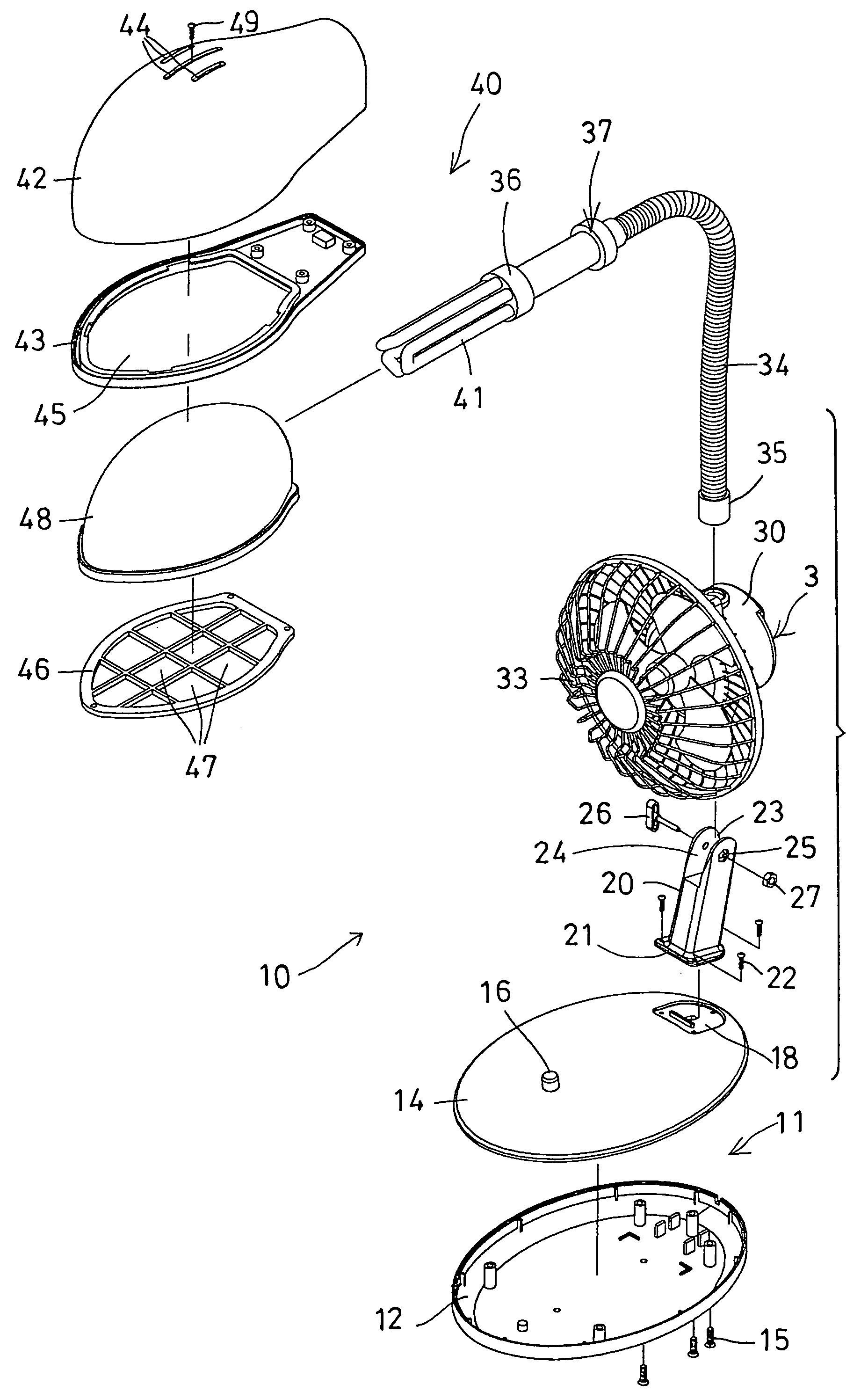
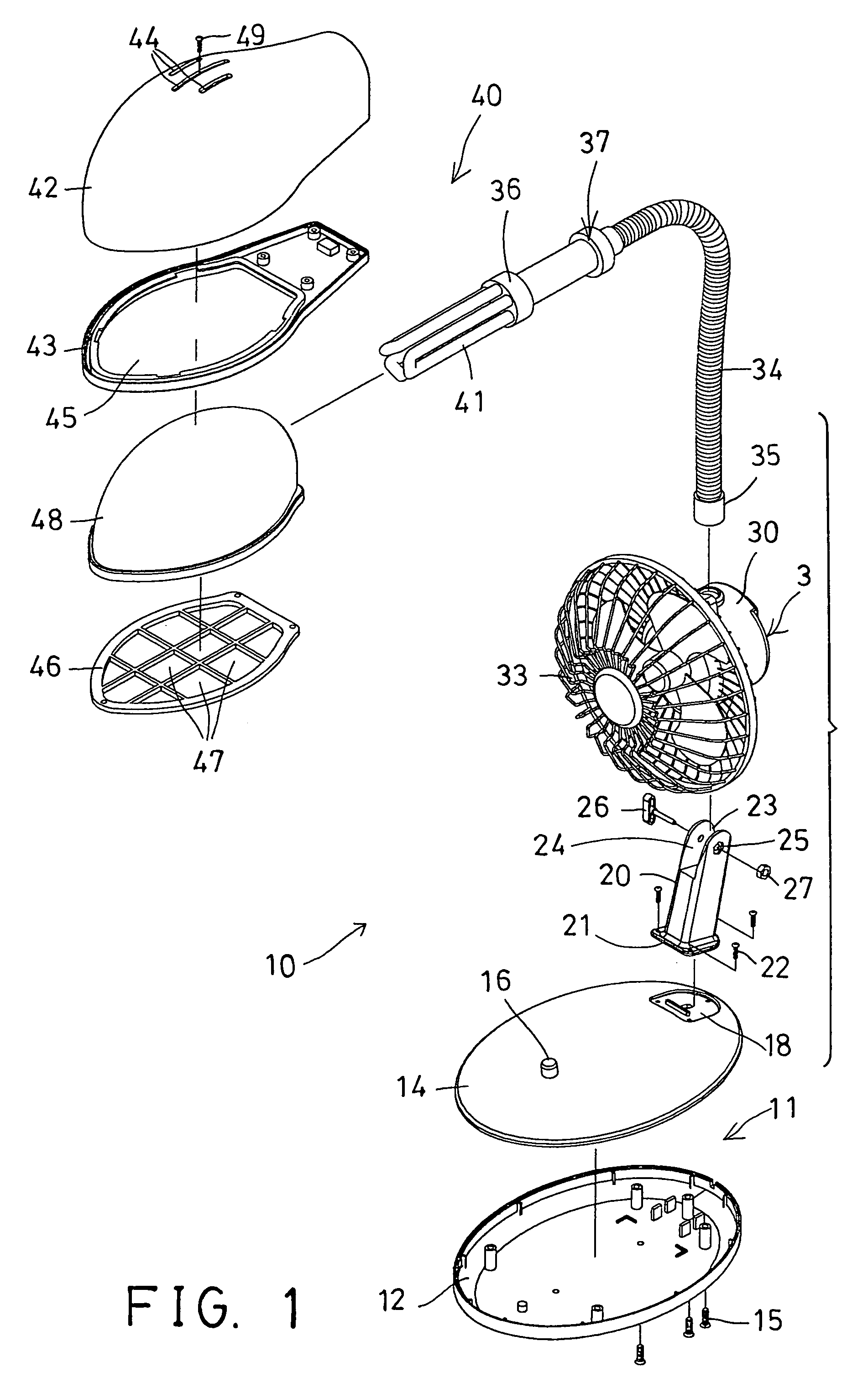
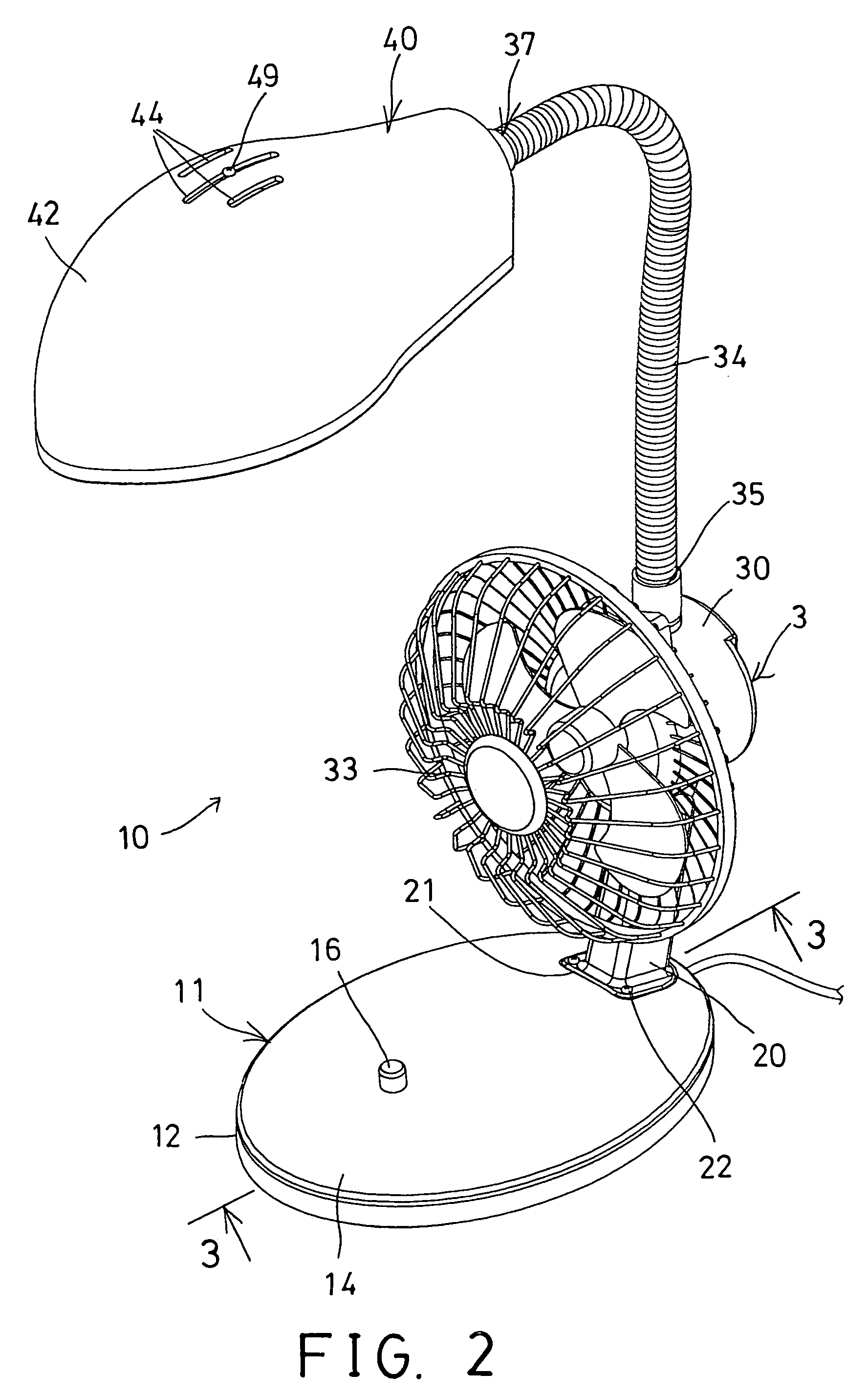
[0026]Referring to the drawings, and initially to FIGS. 1–3, a light and fan device combination 10 in accordance with the present invention comprises a base 11 including such as a lower receptacle 12 and an upper cover 14 secured together with such as fasteners 15, and including one or more switch buttons 16 provided thereon, such as provided on the upper cover 14, for actuating or controlling the light and fan device combination 10. The base 11 further includes a recess 18 formed in the upper portion thereof, such as formed in the upper portion of the upper cover 14.

[0027]A stand 20 includes a lower portion 21 engaged in the recess 18 of the base 11, and secured to the base 11 with such as fasteners 22, and includes a channel 23 formed in the upper portion of the stand 20 and defined between two flaps 24 each of which includes an orifice 25 formed therein, for receiving a fastener 26 and a lock nut 27. A fan device 3 includes a motor housing 30 having an extension 31 extended downw...


PUM


Abstract

A light and fan device combination includes a base, a stand disposed on the base, a fan device disposed on top of the stand, for generating air streams, an extension attached to the fan device, and a light device attached to the extension, for generating lights, and for preventing the light device from being affected by the fan device. The fan device includes a motor housing having an extension rotatably secured to the stand. The extension includes a socket for attaching the light device. The light device includes an upper casing and a lower casing secured together. The lower casing includes an opening for attaching a screen.

Description

BACKGROUND OF THE INVENTION[0001]1. Field of the Invention[0002]The present invention relates to a light and fan device combination, and more particularly to a light and fan device combination having a light device and a fan device separated from each other for being operated properly.[0003]2. Description of the Prior Art[0004]Typical light devices may be provided for generating lights in order to light objects, and the conventional fan devices may be provided for generating air streams or for circulating airs in order to dissipate heat or the like.[0005]Particularly, during the hot or summer days, the typical light devices may also generate light and heat such that the users may feel hot particularly when the typical light devices are energized or are operated.[0006]For heat dissipating purposes, the users may have to spend additional money and to prepare a separate fan device, and disposed the fan device beside him, in order to generate air streams or to circulate airs.[0007]U.S. ...

Claims


Application Information

Patent Timeline
IPC IPC(8): F21V33/00F21S13/12
CPCF04D25/08F21S6/002F21S6/003F21V33/0096F21V21/32
Inventor CHOU, MING SHI
Owner CHOU MING SHI
Learn More