Electrical connecting device having a cover with a latch

a technology of electrical connection device and latch, which is applied in the direction of coupling device connection, securing/insulating coupling contact member, electrical apparatus, etc., can solve the problem and achieve the effect of not being easily disengaged

Active Publication Date: 2006-12-12
JST MFG CO LTD
View PDF10 Cites 13 Cited by
  • Summary
  • Abstract
  • Description
  • Claims
  • Application Information

AI Technical Summary

Benefits of technology

[0006]According to this structure, since the convex part formed on the cover element is engaged with the concave part formed in the opening of the female connector component, the cover element is mechanically locked onto the female connector component and is not easily disengaged even when an external force acts thereon. Additionally, since the cover element with which the upper opening of the male connector component is covered and the female connector component are locked together, a state is reached in which the male connector component and the cover element are both locked onto the female connector component. Therefore, it is possible to obtain the electrical connecting device in which the cover element is not easily disengaged even when an external force acts thereon and in which the male connector component and the cover element are firmly fitted to the female connector component.

Problems solved by technology

According to this structure, since the convex part formed on the cover element is engaged with the concave part formed in the opening of the female connector component, the cover element is mechanically locked onto the female connector component and is not easily disengaged even when an external force acts thereon.

Method used


Image

  • Electrical connecting device having a cover with a latch
  • Electrical connecting device having a cover with a latch
  • Electrical connecting device having a cover with a latch

Examples


Embodiment Construction

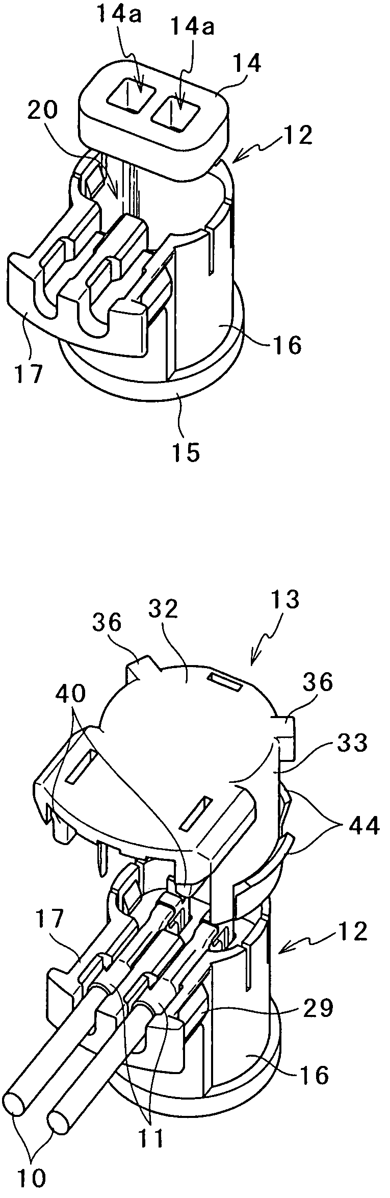
[0022]With reference to the attached drawings, a description will be hereinafter given of a best mode for carrying out the present invention. The present invention is suitable to be applied as an electrical connecting device for a squib that is ignited by applying an electric current to a gas generator in a vehicular air bag system. Although an embodiment in this case will be described, the present invention can be widely and variously applied and can be applied in many different environments and for various kinds of objects.

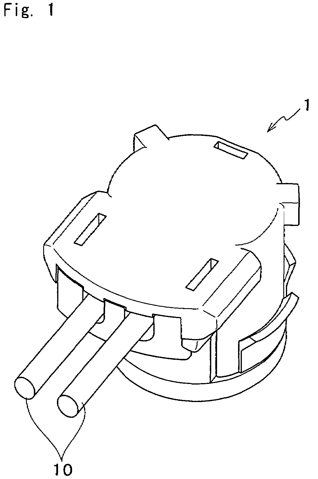
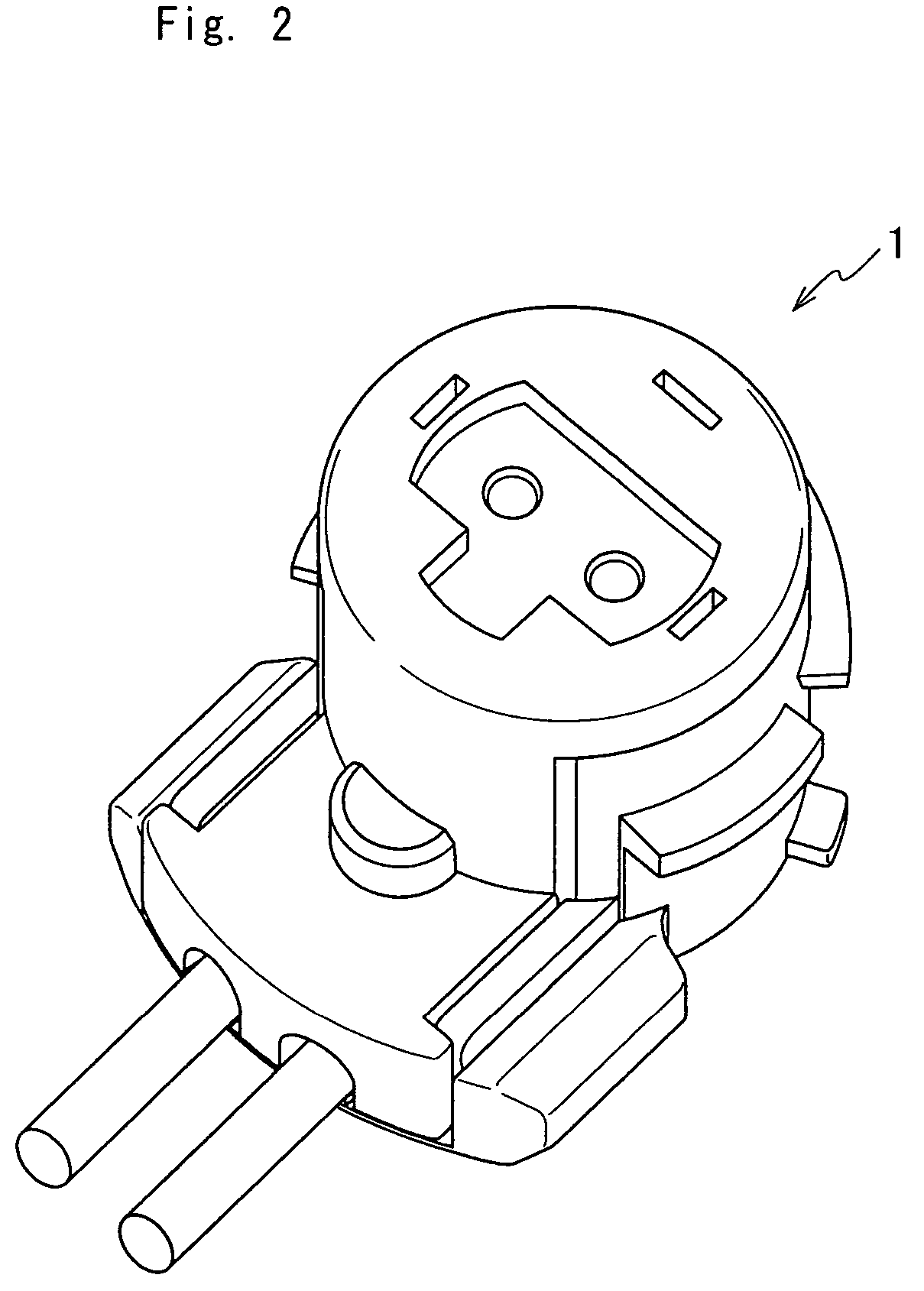
[0023]FIG. 1 is a perspective view of an electrical connecting device 1, seen from above, according to an embodiment of the present invention, and FIG. 2 is a perspective view of the electrical connecting device 1 turned upside down from the state of FIG. 1 (i.e., with a bottom of the electrical connecting device 1 upward). FIG. 3 is a plan view showing a state in which the electrical connecting device 1 is fitted and connected to a connector component 2 to be c...


PUM


Abstract

An electrical connector comprises a male connector component supporting connecting terminals, which are electrically connected to to-be-connecting terminals of a female connector element, and a cover element attached to the male connector component to the connecting terminals. The male connector component includes a peripheral wall, which forms a cavity for a ferrite member and which includes flexible latches to restrain movement of the ferrite member. The cover element includes an outer peripheral wall adapted for fitting the peripheral wall of the male connector component. The cover element also includes a latching part disposed on an outer surface of the outer peripheral wall and expanding outward. The latching part engages with a recess formed in an opening of the female connector component when the cover element is fitted into the opening together with the male connector component.

Description

TECHNICAL FIELD[0001]The present invention relates to an electrical connecting device that has a male connector component, which supports a pair of connecting terminals, and a cover element fitted to the male connector component and that is connected to a female connector component supporting a pair of to-be-connected terminals.BACKGROUND ART[0002]A device disclosed in Japanese Published Unexamined Patent Application No. 2002-33153 is conventionally known as an electrical connecting device that has a male connector component, which supports a pair of connecting terminals, and a cover element fitted to the male connector component and that is connected to a female connector component supporting a pair of to-be-connected terminals. The electrical connecting device disclosed in this publication (No. 2002-33153) is a plug connector that is connected to a socket connector so as to realize an ignition circuit of a detonator of an air bag gas generator for vehicles. This electrical connect...

Claims


Application Information

Patent Timeline
Patent Type & Authority Patents(United States)
IPC IPC(8): H01R13/627H01R13/42H01R13/506H01R13/645
CPCH01R13/6277H01R13/645Y10S439/942
Inventor SHINDO, SATORU
Owner JST MFG CO LTD
Why Eureka
Try Eureka