Pilot-controlled electromagnetic valve system

a technology of electromagnetic valves and electromagnetic valves, which is applied in the direction of valve housings, valve operating means/release devices, and washers, etc., can solve the problem that the screw b>11/b> may come off undesired

Active Publication Date: 2007-05-15
SMC CORP
View PDF10 Cites 6 Cited by
  • Summary
  • Abstract
  • Description
  • Claims
  • Application Information

AI Technical Summary

Benefits of technology

[0014]In the pilot-controlled electromagnetic valve system according to the present invention, a washer engagement groove is formed at a bearing surface on the top of an electromagnetic valve block. An inwardly sloped washer having an engagement portion at the inner side thereof is fitted on a screw. The engagement portion is engaged with a side wall of the washer engagement groove. As the screw is tightened, the washer is deformed. Consequently, resilient force for preventing loosening of the washer occurs, thereby making it difficult for the washer from disengaging from the washer engagement groove. Accordingly, the electromagnetic valve block is surely secured to the manifold block even if the electromagnetic valve block is one at an end of a series of electromagnetic valve blocks constituting a valve manifold, or provided singly.

Problems solved by technology

In such a case, the screw 11 may come off undesirably.

Method used


Image

  • Pilot-controlled electromagnetic valve system
  • Pilot-controlled electromagnetic valve system
  • Pilot-controlled electromagnetic valve system

Examples


Embodiment Construction

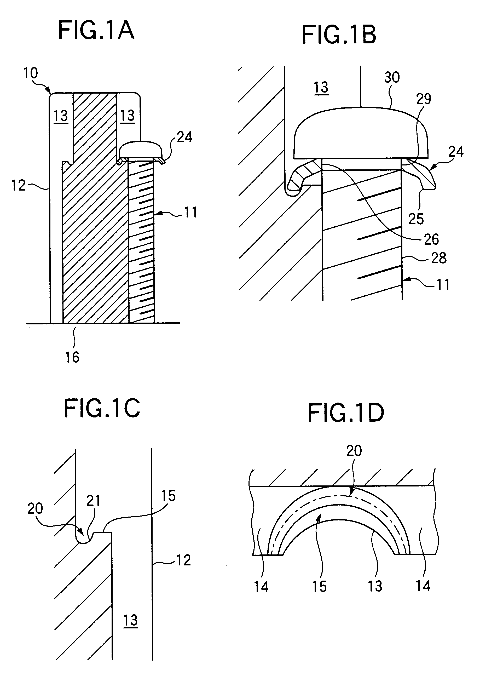
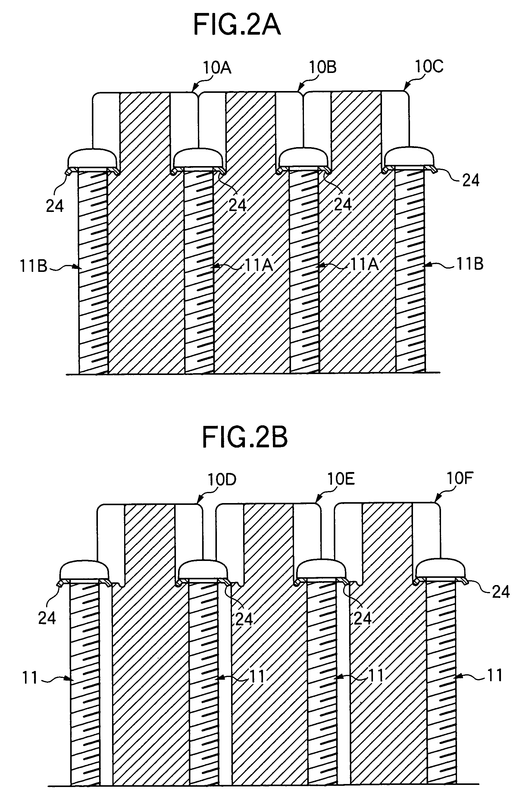
[0028]FIGS. 1A to 2B show an embodiment of the pilot-controlled electromagnetic valve system according to the present invention. In FIGS. 1A to 2B, the same members or portions as those in FIGS. 3A to 3D are denoted by the same reference numerals as in FIGS. 3A to 3D, and a description thereof will be given briefly.

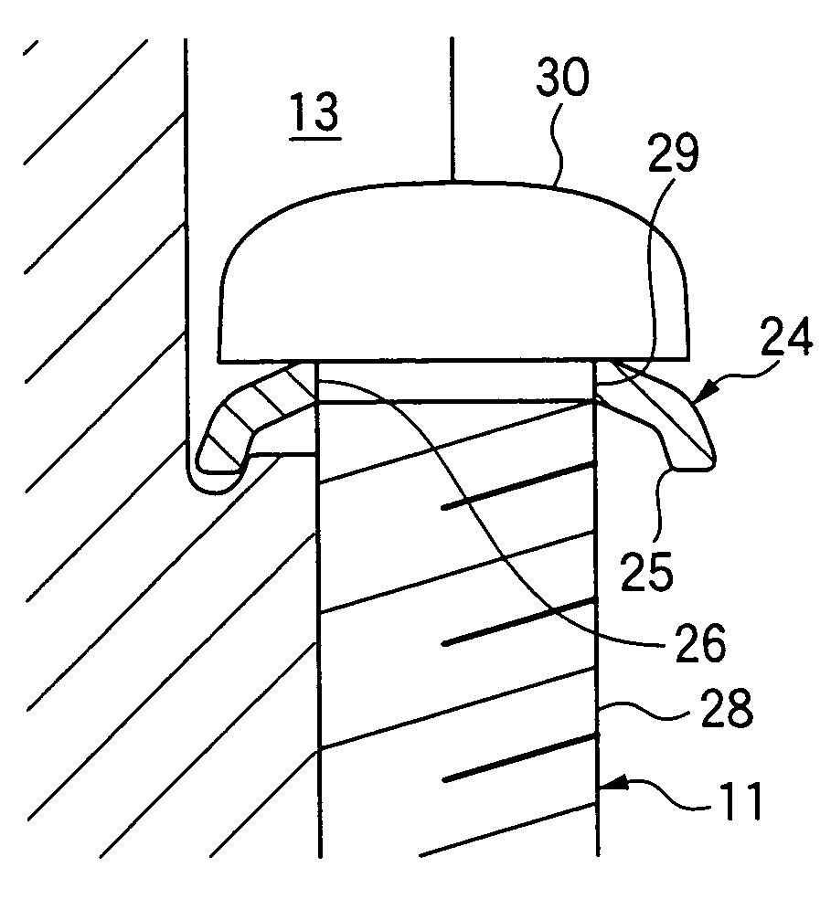
[0029]The feature of the embodiment of the present invention is as follows. A washer engagement groove 20 is formed at each bearing surface 15. An inwardly sloped washer 24 having an engagement portion 25 at the inner side thereof is fitted on a screw 11. The engagement portion 25 of the washer 24 is engaged with a side wall of the washer engagement groove 20. It should be noted that the washer 24 is made from a ring formed by boring an insertion hole in the center of a disk. The ring is formed into an approximately umbrella-like configuration, for example. The lower side of the approximately umbrella-like washer 24 is defined as the inner side.

[0030]As will be understood...


PUM


Abstract

A pilot-controlled electromagnetic valve system has an electromagnetic valve block mounted on the top of a manifold block. A bearing surface is formed on the top of the electromagnetic valve block at a position adjacent to a screw accommodating recess formed on a joint surface at a side of the electromagnetic valve block. A washer engagement groove is formed at the bearing surface. An inwardly sloped washer having an engagement portion at the inner side thereof is fitted on a screw. The engagement portion is engaged with a side wall of the washer engagement groove. Thus, the electromagnetic valve block is surely secured to the manifold block with the screw even if the electromagnetic valve block is one at an end of a series of electromagnetic valve blocks constituting a valve manifold, or provided singly.

Description

BACKGROUND OF THE INVENTION[0001]1. Field of the Invention[0002]The present invention relates to a pilot-controlled electromagnetic valve system in which an electromagnetic valve block is secured to the top of a manifold block of a valve manifold.[0003]2. Description of the Related Art[0004]Japanese Patent Application Unexamined Publication (KOKAI) No. 2002-250463 (patent document 1) discloses a pilot-controlled electromagnetic valve system in which a multiplicity of electromagnetic valve blocks are mounted on a single manifold block (manifold base) in such a manner that each pair of adjacent electromagnetic valve block are joined together, and the electromagnetic valve blocks are secured to the manifold block by using screws. Japanese Patent Application Unexamined Publication (KOKAI) No. 2000-283324 (patent document 2) discloses an electromagnetic valve system in which a necessary number of electromagnetic valve block and manifold block combinations are provided in such a manner th...

Claims


Application Information

Patent Timeline
Patent Type & Authority Patents(United States)
IPC IPC(8): F16K31/00F15B13/00F15B13/08F16B5/02F16B9/02F16B43/00F16K27/00F16K31/06
CPCF15B13/0814F15B13/0821F15B13/0832F15B13/0857F16B5/02F16B43/00F16K27/00
Inventor FUKANO, YOSHIHIROOSHIMA, MASAYUKI
Owner SMC CORP
Why Eureka
Try Eureka