Apparatus for correction of leg deformities

a technology for rectification and tibia, applied in the field of orthopaedic devices for rectification of leg deformities, can solve the problems of unnecessarily slow, unnecessary slowness, and abnormalities, and achieve the effect of substantial flexibility

Active Publication Date: 2006-12-12
MOLINO JOSEPH L +1
View PDF14 Cites 7 Cited by
  • Summary
  • Abstract
  • Description
  • Claims
  • Application Information

AI Technical Summary

Benefits of technology

[0010]To maintain the correct orientation of the ankle complex, an ankle joint is utilized which is substantially rigid in the proximal to distal direction and having substantial flexibility in the Coronal and Sagital planes. This allows the knee axis and ankle axis to remain in a neutral orientation while the required corrective forces are being applied.
[0011]The dynamic portion of the orthotic device of the invention is associated with the distal receiving element which is pivotal in the Coronal plane about an axis at the level of the varus deformity. This allows the corrective force is directed at the precise area of deformity without exerting pressure that could cause secondary deformities.

Problems solved by technology

This results in an abrupt varus deformity in the proximal tibia and is also associated with an internal torsion of the tibia.
These procedures can create other misalignments, are incremental, and unnecessarily slow.
The abnormality exists due to the continued growth of the lateral epiphysis and the stunted growth of the medial epiphysis causing a curving of the leg.
Currently, the disease is treatable by application of conventional braces with limited success and an unnecessarily long treatment period.
The known prior art devices utilized for the correction of the tibia are very restrictive in nature and are typically utilized when the leg of a patient is in a straight position.
Unfortunately, during application of the three point pressure system, deformation and correction occurs not only at the tibia, which needs to be corrected, but the compensatory deformation and correction of the bone structure also occurs at the femur, which does not need to be corrected.
This is because the treatment of the femur introduces additional and undesired deformity to the child's limb.
Thus, there has been a long felt and unsolved need for a medical device and procedure adapted for treatment of Blount's disease and capable of overcoming the shortcomings of the prior art.

Method used


Image

  • Apparatus for correction of leg deformities
  • Apparatus for correction of leg deformities
  • Apparatus for correction of leg deformities

Examples


Embodiment Construction

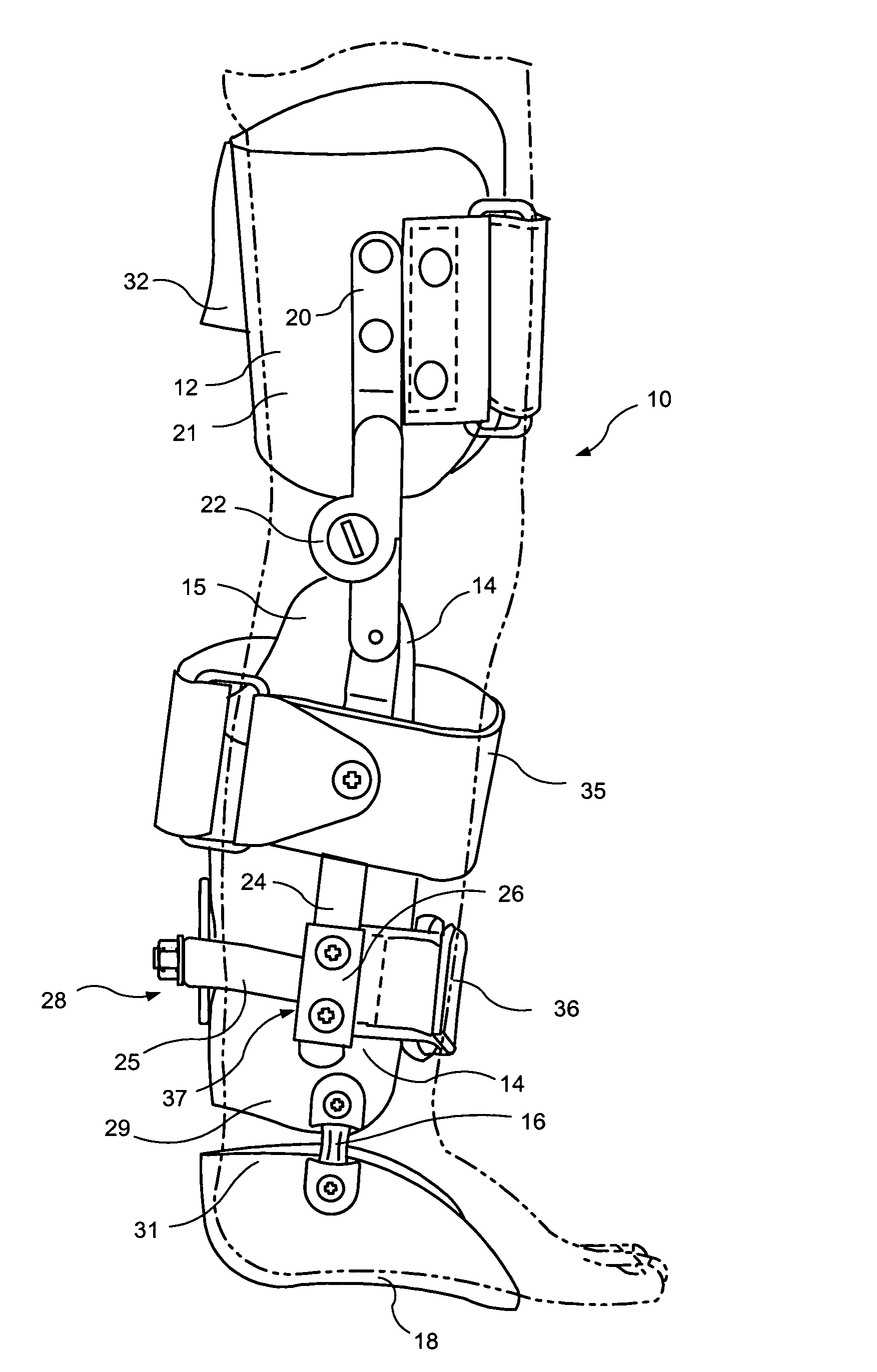
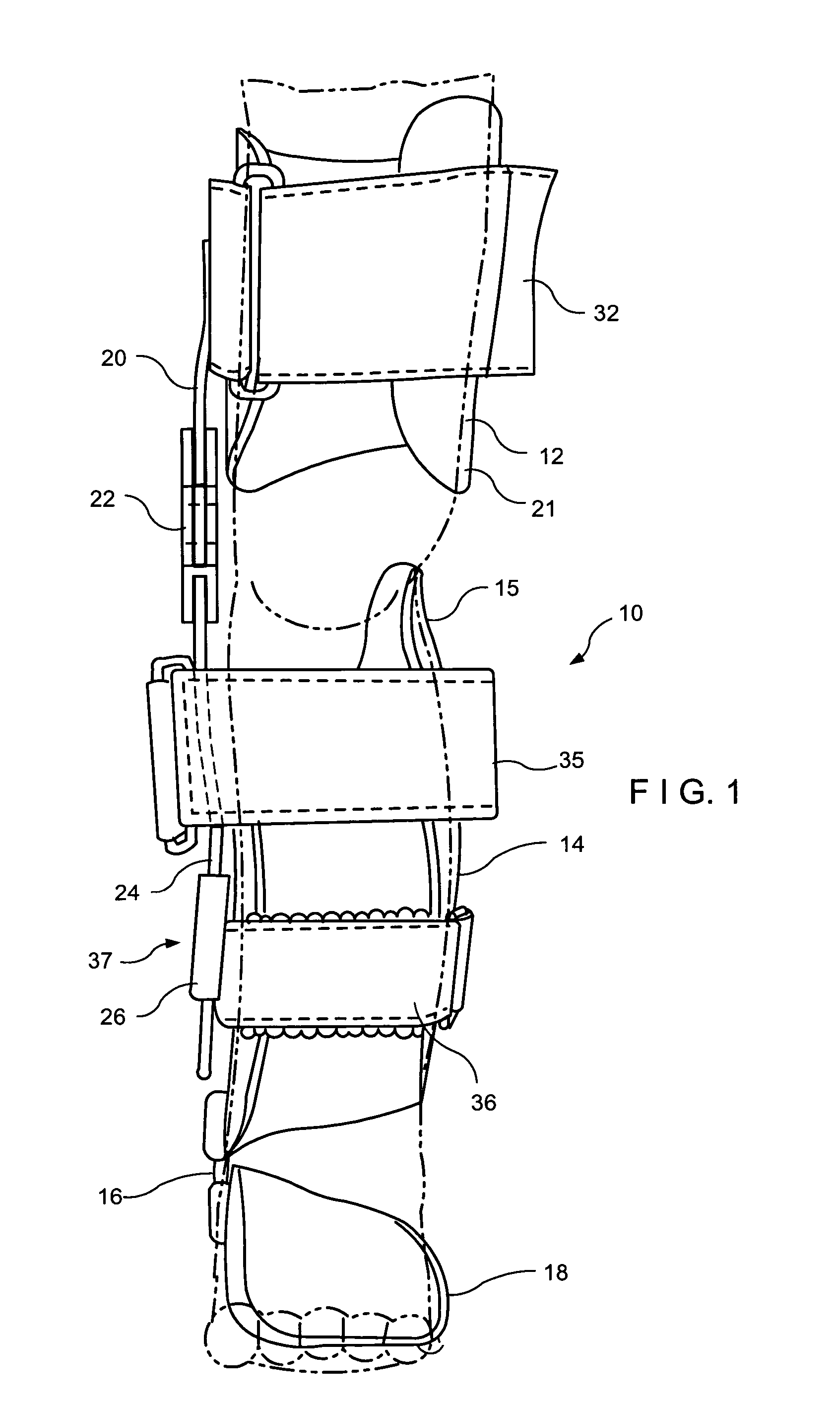
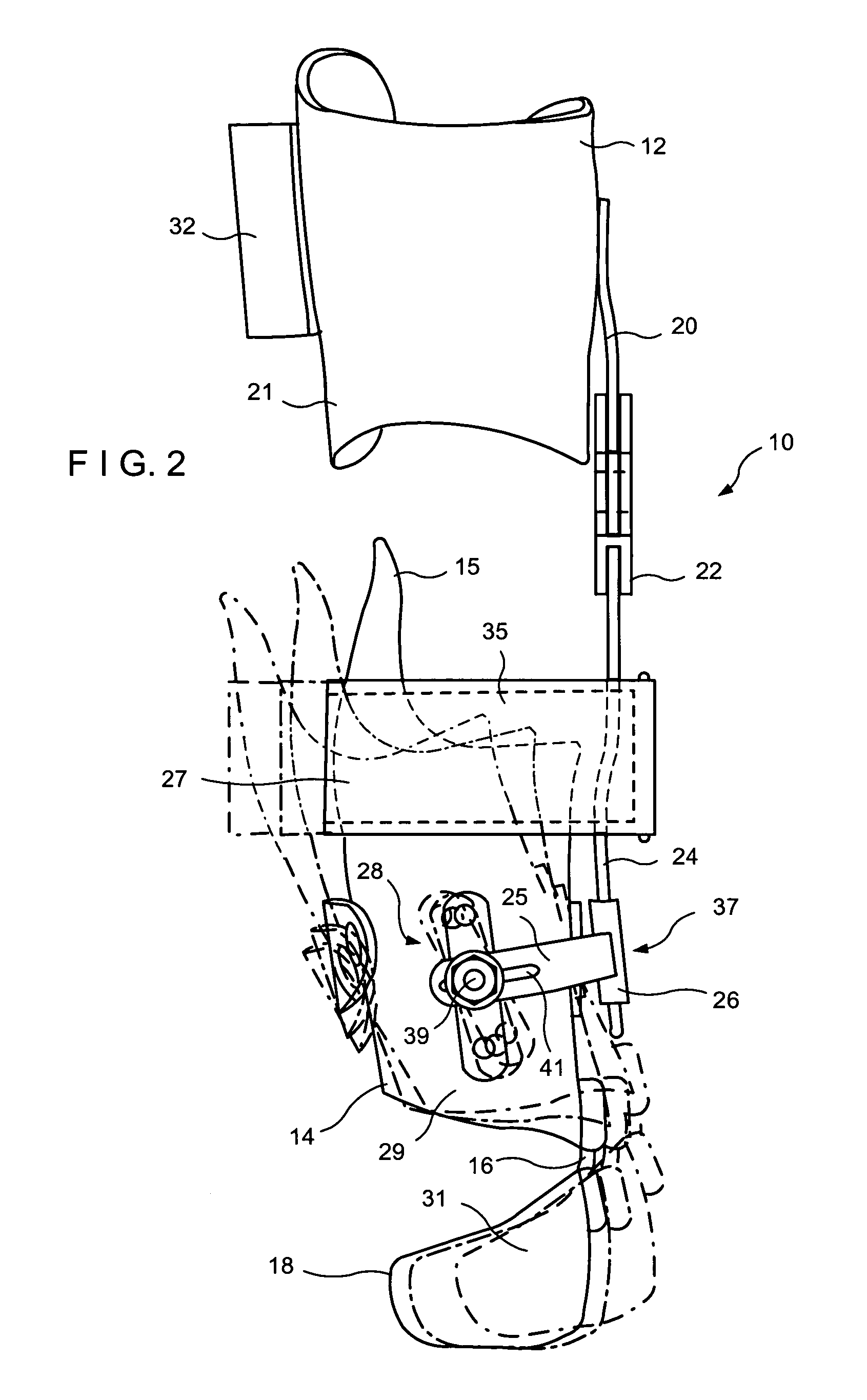
[0026]Referring now more specifically to FIGS. 1–8 of the drawings of the application. An orthotic device or apparatus 10 of the invention consists of a proximal cuff or proximal receiving element 12 adapted to receive an upper thigh area and a distal tibial cuff or distal receiving element 14 adapted to receive a lower leg area or a calf of a human limb. An ankle joint 16 is provided between the distal receiving element 14 and a foot supporting arrangement 18 adapted to receive a foot of a patient On the medial side the proximal receiving element 12 is attached by a proximal strut or proximal connecting element 20 to one side of a knee joint 22. A distal strut or distal connecting element 24 extends from another side of the knee joint 22 and is adapted for connection to the distal receiving element 14. This design requires only a single proximal connecting element 20 associated with the medial side of the proximal receiving element 12 and a single distal connecting element 24 assoc...


PUM


Abstract

An orthotic device is formed with a stationary proximal receiving element adapted to receive at least a portion of a thigh region of a human limb and a distal receiving element adapted to receive a lower region of the human limb. The distal receiving element is pivotally movable with respect to the proximal receiving element by forces applied to a proximal region of the distal receiving element.

Description

[0001]This non-provisional application claims priority under 35 USC 119(e) of U.S. Provisional Application Ser. No. 60 / 495,351 filed by Joseph L. Molino and Michael Rebarber, on Aug. 15, 2003.FIELD OF THE INVENTION[0002]The present invention relates generally to medical devices, and more specifically, it relates to an orthotic device for correction of leg deformities.BACKGROUND OF THE INVENTION[0003]Blount's disease is a progressive disease that affects the varus angle of the tibia in children that is correctable with proper treatment. This disease is a progressive developmental condition that is characterized by disordered endochondral ossification of the medial tibial physis. This results in an abrupt varus deformity in the proximal tibia and is also associated with an internal torsion of the tibia. Current treatment of Blount's disease includes use of static orthotic devices or surgical procedure also known as tibial osteotomy. These procedures can create other misalignments, are...

Claims


Application Information

Patent Timeline
Patent Type & Authority Patents(United States)
IPC IPC(8): A61F5/00A61F5/37A61F5/01
CPCA61F5/0102
Inventor MOLINO, JOSEPH L.REBARBER, MICHEAL
Owner MOLINO JOSEPH L
Why Eureka
Try Eureka