
Underfilling process in a molded matrix array package using flow front modifying solder resist

a technology of molded matrix array and flow front, which is applied in the manufacture of printed circuits, basic electric elements, printed circuit assembling, etc., can solve the problems of reducing the reliability of the package, the molding process, and the possibility of air trapped under the di

Inactive Publication Date: 2006-12-19
INTEL CORP
View PDF12 Cites 12 Cited by
  • Summary
  • Abstract
  • Description
  • Claims
  • Application Information

AI Technical Summary

Problems solved by technology

Variations in the mold flow both on top and on bottom of the flip chips can cause multiple problems in the molding process.
In addition, because the molding compound can flow around and over each die prior to a molding compound underfilling the die, air may be trapped under the die.
The trapped air under the die may cause a void that will decrease reliability in the package.
However, using a low pressure region or poking a hole in the substrate may increase the cost of producing the package and may reduce the reliability of the package.

Method used


Image

  • Underfilling process in a molded matrix array package using flow front modifying solder resist
  • Underfilling process in a molded matrix array package using flow front modifying solder resist
  • Underfilling process in a molded matrix array package using flow front modifying solder resist

Examples


Embodiment Construction

[0021]In the following description numerous specific details are set forth. However, it is understood that the embodiments of the invention may be practiced without these specific details. In other instances, well-known details such as particular materials or methods have not been shown in detail in order not to obscure the understanding of this description.

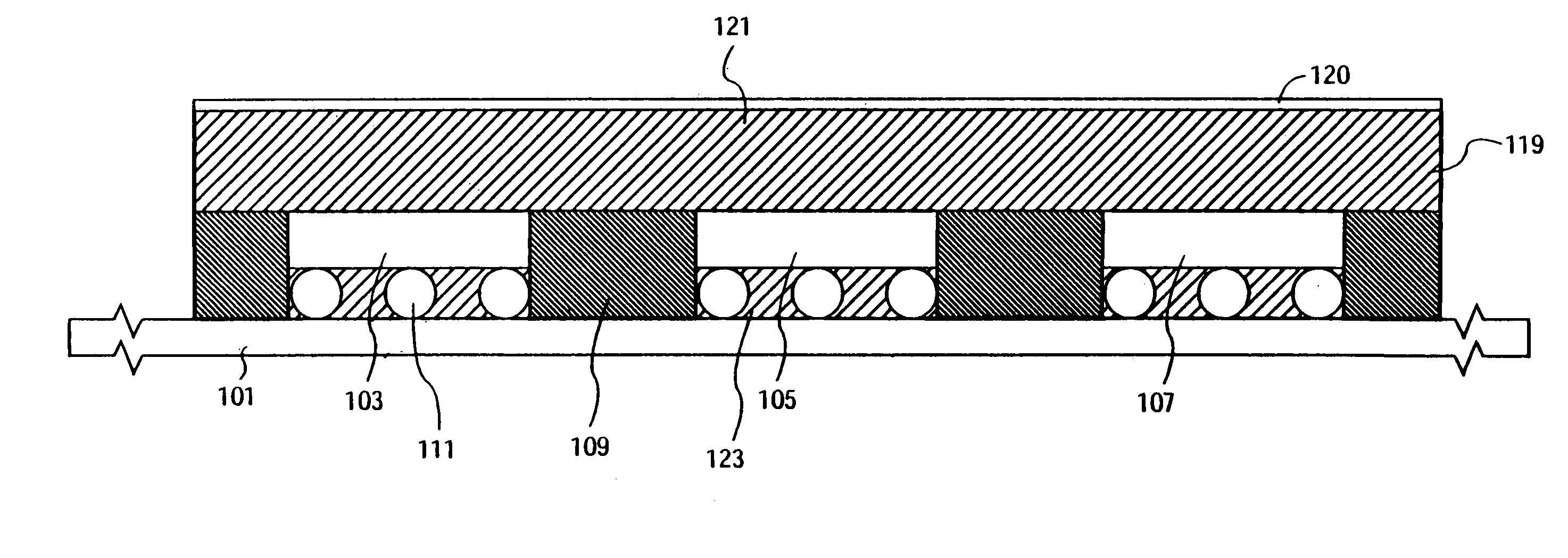
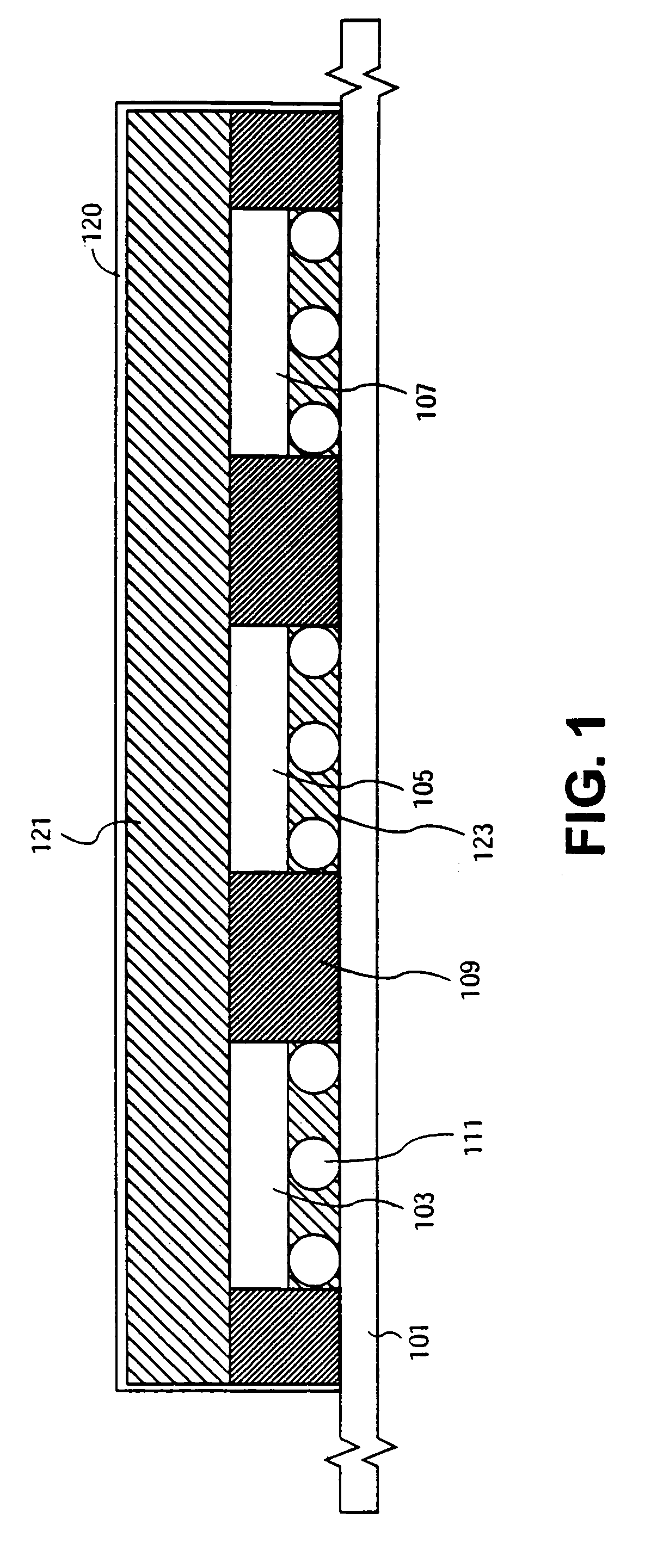
[0022]Referring to FIG. 1, a side view of an embodiment of the invention is shown having two separate mold flows. In one embodiment of the invention, the top mold flow 121 flowing between the top of the dice 103, 105, and 107 and the mold chase 120, and the bottom mold flow 123 between the dice 103, 105, and 107 and the package substrate 101, are kept separate by flow modifier 109. By splitting the mold flow into two separate mold flows using the flow modifier 109, the top mold flow 121 may be prevented from wrapping over the dice 103, 105, and 107. Without the flow modifier 109, the bottom mold flow 123 and the resulting overwra...


PUM


Abstract

Placing a flow modifier on a package substrate to create two flow fronts on a molded matrix array package. A flow modifier may be laid on a package substrate to a height that blocks off the bottom of other substrates (e.g., dice) coupled to the package substrate. By separating the top flow front and the bottom flow front, this process prevents the top flow front from wrapping around the sides of the substrates and trapping air below each substrate and in front of the bottom flow front.

Description

[0001]This is a Divisional Application of Ser. No. 10 / 287,318 filed Nov. 4, 2002, which is presently pending.BACKGROUND[0002]1. Technical Field[0003]An embodiment of the invention relates generally to manufacturing electronic circuit assemblies, and in particular to the molding process of a molded matrix array package.[0004]2. Description of the Related Art[0005]Molded matrix array packages are underfilled and overmolded in a single step. This may include several flip chips mounted on a substrate. After underfilling and overmolding all of the flip chips on the substrate, the individual flip chips may be singulated into packages. Variations in the mold flow both on top and on bottom of the flip chips can cause multiple problems in the molding process. In addition, because the molding compound can flow around and over each die prior to a molding compound underfilling the die, air may be trapped under the die. The trapped air under the die may cause a void that will decrease reliabilit...

Claims


Application Information

Patent Timeline
IPC IPC(8): H01L23/31H01L21/56H05K3/34
CPCH01L21/563H01L2224/73203H05K3/3452H01L2224/16225H01L2224/32225H01L2224/73204H01L2924/00H01L2924/00014H01L2224/0401
Inventor MANEPALLI, RAHUL N.KRISHNAN, SARAVANANCHEE, CHOONG KOOI
Owner INTEL CORP
Learn More