Contractable and expandable tubular wellbore system

a tubular wellbore and wellbore technology, applied in the field of tubular systems, can solve the problems of lower when compared to the resistance of conventional tubular elements without hinges, and achieve the effect of reducing the collapse resistance of the tub

Inactive Publication Date: 2006-12-26
SHELL USA INC
View PDF14 Cites 23 Cited by
  • Summary
  • Abstract
  • Description
  • Claims
  • Application Information

AI Technical Summary

Benefits of technology

[0008]By virtue of the staggered arrangement of the respective sets of hinges it is achieved that each hinge of the outer tube is arranged opposite a section of the inner tube of full wall thickness, so that inadvertent / unintentional bending of the hinges of the outer tube (when in the expanded mode) is prevented.

Problems solved by technology

A drawback of the known system is that the collapse resistance of the tube, when in the expanded mode, is lower than conventional tubular elements without hinges.

Method used


Image

  • Contractable and expandable tubular wellbore system
  • Contractable and expandable tubular wellbore system
  • Contractable and expandable tubular wellbore system

Examples


Embodiment Construction

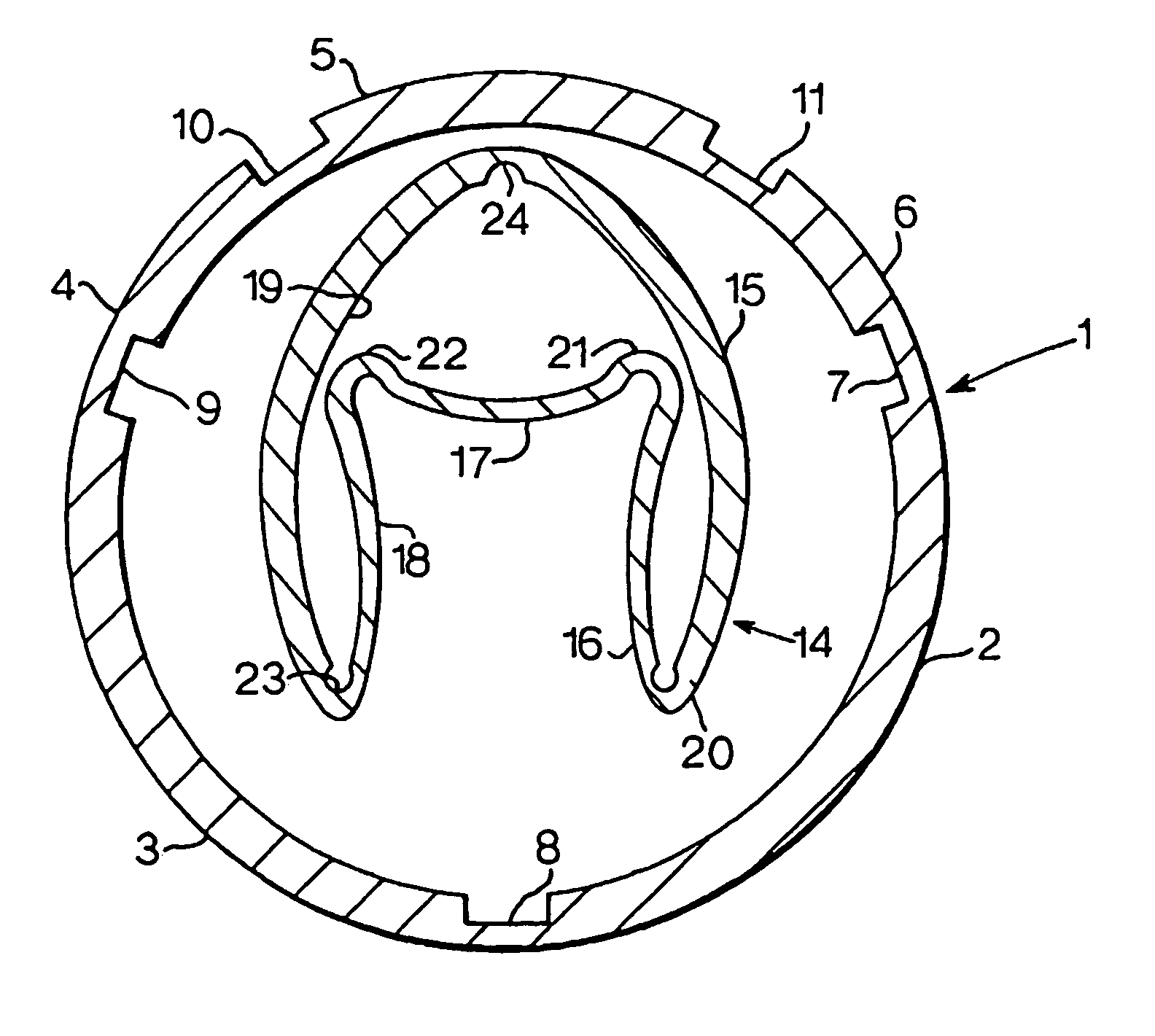
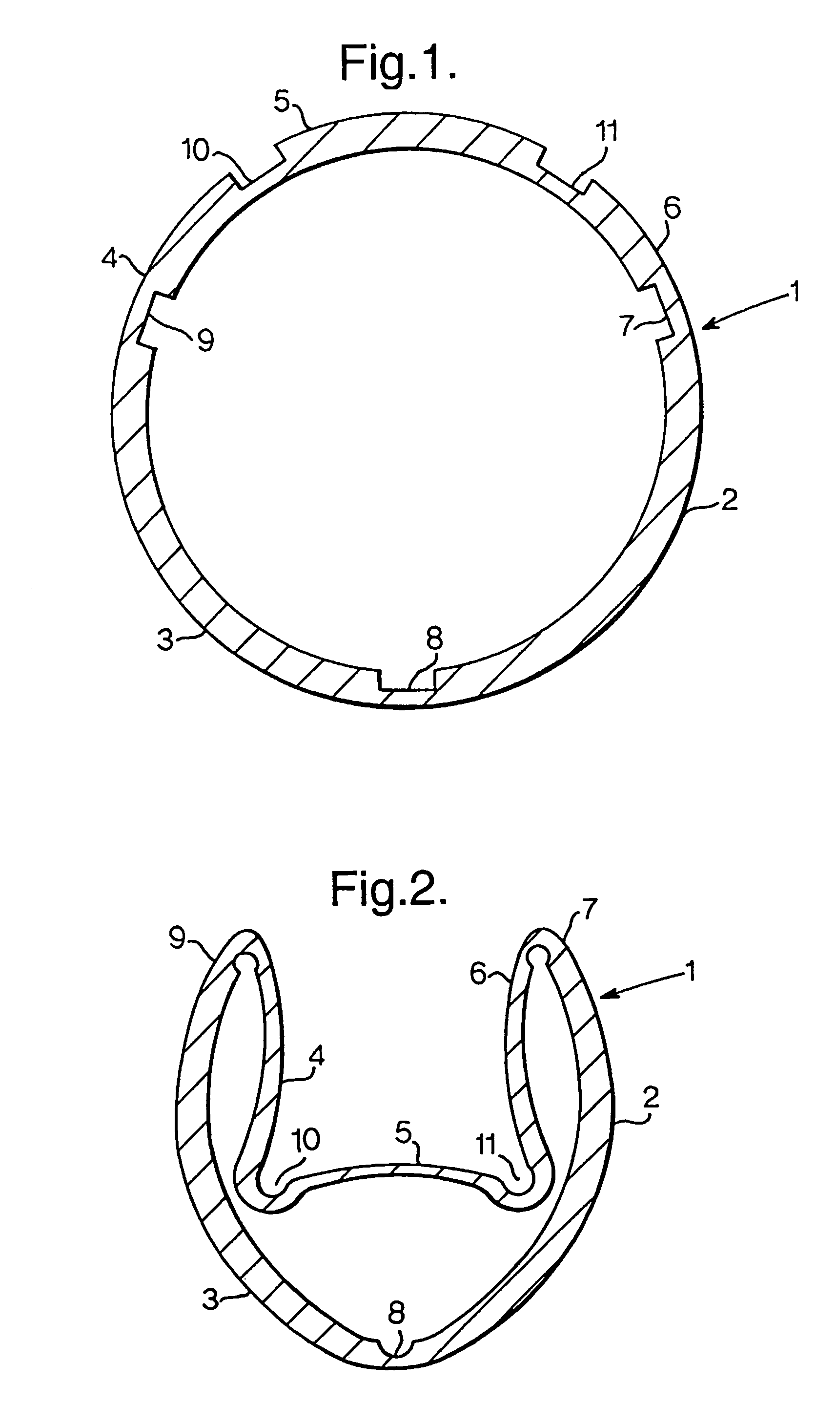
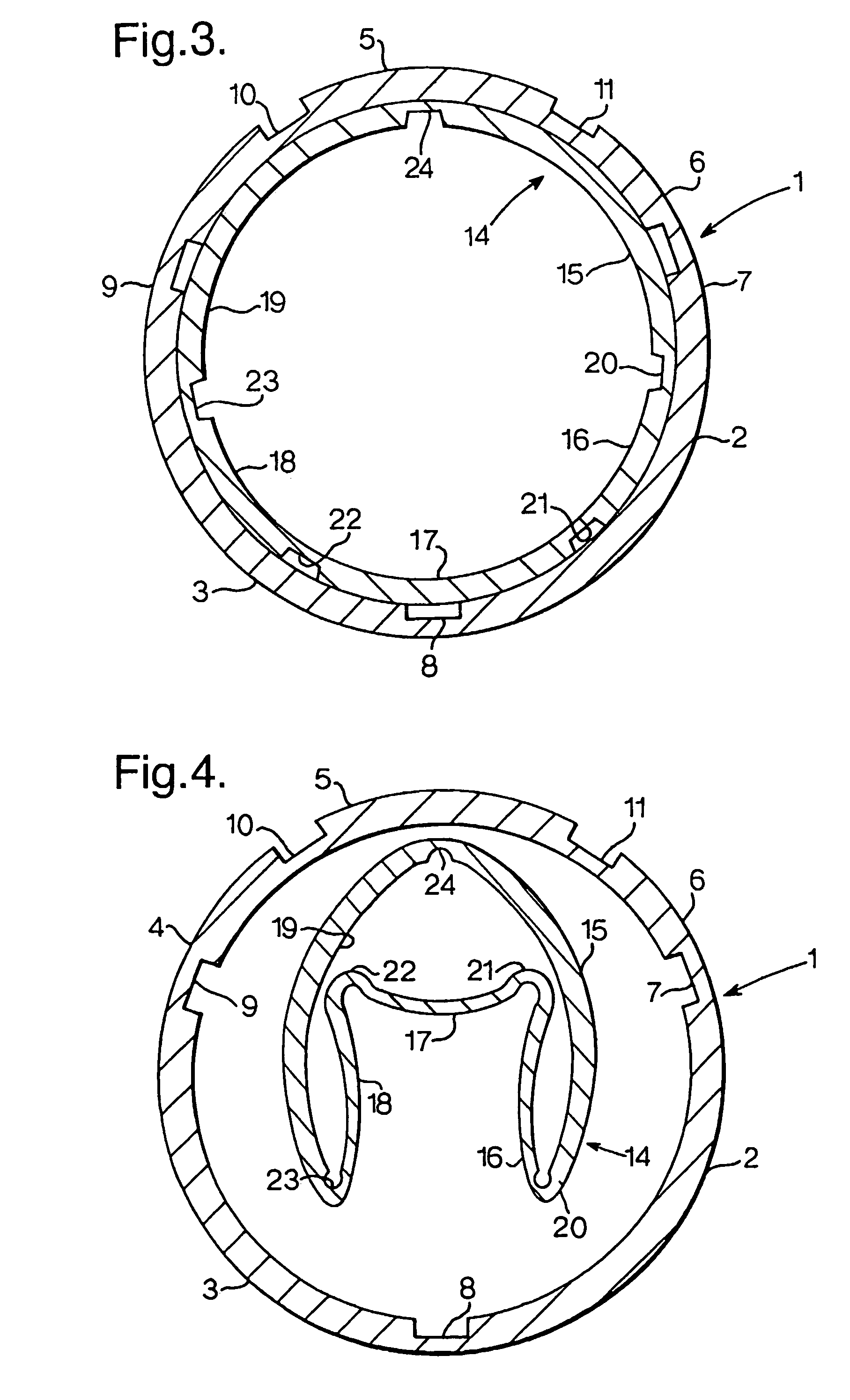
[0014]Referring to FIG. 1 there is shown a wellbore casing in the form of tubular member 1 which is to be installed in a wellbore (not shown) which has been drilled in an earth formation, whereby the tubular member 1 in the final position thereof is either directly surrounded by the rock formation (not shown) optionally with a cement bonding agent or rubber sleeve inbetween, or is surrounded by another wellbore tubular member. The tubular member 1 will be referred hereinafter as an “outer tube 1” in order to distinguish from an “inner tube” referred to hereinafter.

[0015]The outer tube 1 has five arcuate sections 2, 3, 4, 5, 6 having a relatively thick wall, and five short sections 7, 8, 9, 10, 11 interconnecting the arcuate sections and having a relatively thin wall. The short sections 7, 8, 9, 10, 11 extend in longitudinal or near longitudinal direction of the outer tube 1. By virtue of their reduced wall thickness, the short sections 7, 8, 9, 10, 11 have a reduced bending stiffnes...


PUM


Abstract

A tubular system arranged in a wellbore, having an outer tube extending into the wellbore and a wall with at least one section of reduced bending stiffness, each section defining a hinge allowing the outer tube to move between a collapsed mode and an expanded mode. An inner tube extends into the outer tube and has a wall with at least one section of reduced bending stiffness, each section defining a hinge allowing the inner tube to move between a collapsed mode and an expanded mode. With the tubes in their respective expanded modes, the inner tube supports the outer tube and is oriented in the outer tube such that each hinge of the inner tube is circumferentially displaced from each hinge of the outer tube.

Description

[0001]The present application claims priority on European Patent Application 01308525.3 filed on 5 Oct. 2001.FIELD OF THE INVENTION[0002]The present invention relates to a tubular system arranged in a wellbore, comprising a tube extending into the wellbore and having a wall with at least one section of reduced bending stiffness, each section of reduced bending stiffness defining a hinge allowing the tube to move between a collapsed mode in which the tube has a relatively small cross-sectional size and an expanded mode in which the tube has a relatively large cross-sectional size.BACKGROUND OF THE INVENTION[0003]WO 99 / 55999 discloses such system wherein the tube forms a wellbore casing which stabilises the borehole wall and prevents collapse of the borehole.[0004]A drawback of the known system is that the collapse resistance of the tube, when in the expanded mode, is lower than conventional tubular elements without hinges.[0005]In accordance with the invention there is provided a tub...

Claims


Application Information

Patent Timeline
Patent Type & Authority Patents(United States)
IPC IPC(8): E21B43/10E21B29/10E21B33/14E21B29/00F16L9/00F16L9/133F16L11/12
CPCE21B43/103E21B29/00
Inventor LOHBECK, WILHELMUS CHRISTIANUS MARIA
Owner SHELL USA INC
Why Eureka
Try Eureka