Dual mode CMUT transducer

A technology of transducers and patterns, applied in induction generators, fluids using vibrations, medical science, etc.

Active Publication Date: 2016-04-13
KONINKLJIJKE PHILIPS NV
View PDF16 Cites 10 Cited by
  • Summary
  • Abstract
  • Description
  • Claims
  • Application Information

AI Technical Summary

Problems solved by technology

[0010] The disadvantage of this solution is that the adjustment of the CMUT transceiver gap has to be pre-defined during manufacture (providing protruding elements or rolling elements)

Method used


Image

  • Dual mode CMUT transducer
  • Dual mode CMUT transducer
  • Dual mode CMUT transducer

Examples


Embodiment Construction

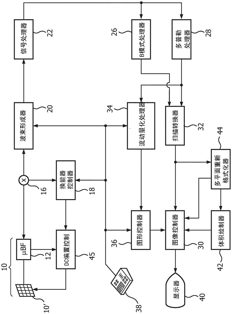
[0053] first reference figure 1 , showing in block diagram form an ultrasonic diagnostic imaging system with a frequency-controlled CMUT probe. exist figure 1 Among them, a CMUT transducer array 10' is provided in an ultrasound probe 10 to transmit ultrasound waves and receive echo information. The transducer array 10' is a one-dimensional or two-dimensional array of transducer elements capable of scanning in a 2D plane or in three dimensions for 3D imaging. The transducer array is coupled to a microbeamformer 12 in the probe, which controls the transmission and reception of signals through the CMUT array elements. Microbeamformers are capable of at least partial beamforming of signals received by groups or "tiles" of transducer elements, as in US Pat. as described. The microbeamformer is coupled by the probe cable to a transmit / receive (T / R) switch 16, which toggles between transmit and receive and when the microbeamformer is not used and the transducer array is directly ...


PUM


Abstract

An ultrasonic diagnostic imaging system comprises a CMUT transducer probe with an array (10') of CMUT cells either of the same or variable diameters operated in a conventional mode during ultrasonic signal reception and a collapsed mode during ultrasonic signal transmission. The frequency response to the CMUT cells is tailored for different clinical applications or continuously varied during echo reception by decreasing the DC bias voltage for the CMUT cells for lower frequency clinical applications, increasing the DC bias voltage for higher frequency clinical applications, or continuously decreasing the DC bias voltage as echoes are received to track the information frequency composition of the returning echo signals.

Description

technical field [0001] The present invention relates to an ultrasonic diagnostic imaging system having a CMUT transducer probe comprising: an array comprising one or more CMUT cells, wherein each CMUT cell has a cell membrane, a membrane electrode, a cell platen (floor), a substrate and a substrate electrode; and a source of DC bias voltage coupled to the membrane electrode and the substrate electrode. Furthermore, the invention relates to a method of operating an ultrasonic diagnostic imaging system. Background technique [0002] Ultrasound transducers used in medical imaging have many properties that enable the production of high quality diagnostic images. Among these, there is wide bandwidth and high sensitivity to low-level acoustic signals at ultrasonic frequencies. Typically, piezoelectric materials with these properties have been made from PZT and PVDF materials, of which PZT is most preferred. However, ceramic PZT materials require significantly different and comp...

Claims


Application Information

Patent Timeline
Patent Type & Authority Applications(China)
IPC IPC(8): B06B1/02
CPCB06B1/02B06B1/0292A61B8/4411A61B8/4438A61B8/4494H02N1/006H02N1/08
Inventor A·V·帕蒂尔J·宋
Owner KONINKLJIJKE PHILIPS NV
Why Eureka
Try Eureka