Dual tapered spring probe

a tapered spring and probe technology, applied in the direction of coupling contact members, coupling device connections, instruments, etc., can solve the problems of mechanical degradation or failure, reduce or degrade the electrical performance of the probe,

Inactive Publication Date: 2006-12-26
INTERCONNECT DEVICES
View PDF41 Cites 51 Cited by
  • Summary
  • Abstract
  • Description
  • Claims
  • Application Information

AI Technical Summary

Benefits of technology

[0003]The present invention provides a contact spring probe with a dual tapered spring with closed coils at eac...

Problems solved by technology

Long signal paths may reduce or degrade the electrical performanc...

Method used


Image

  • Dual tapered spring probe
  • Dual tapered spring probe
  • Dual tapered spring probe

Examples


Embodiment Construction

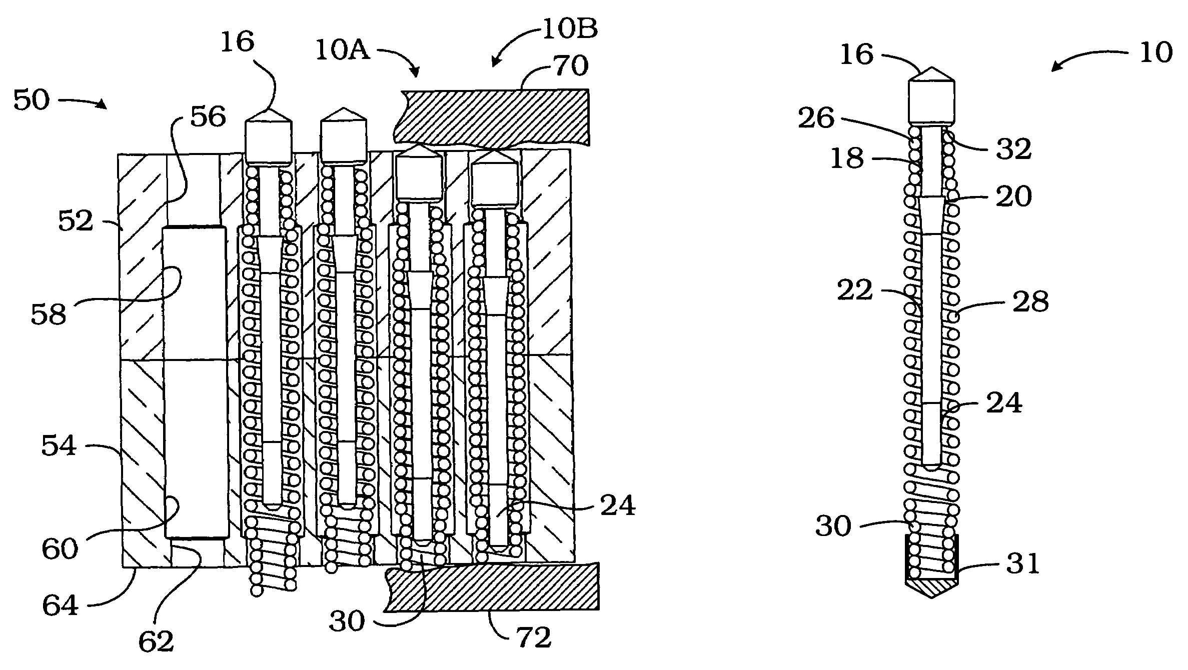
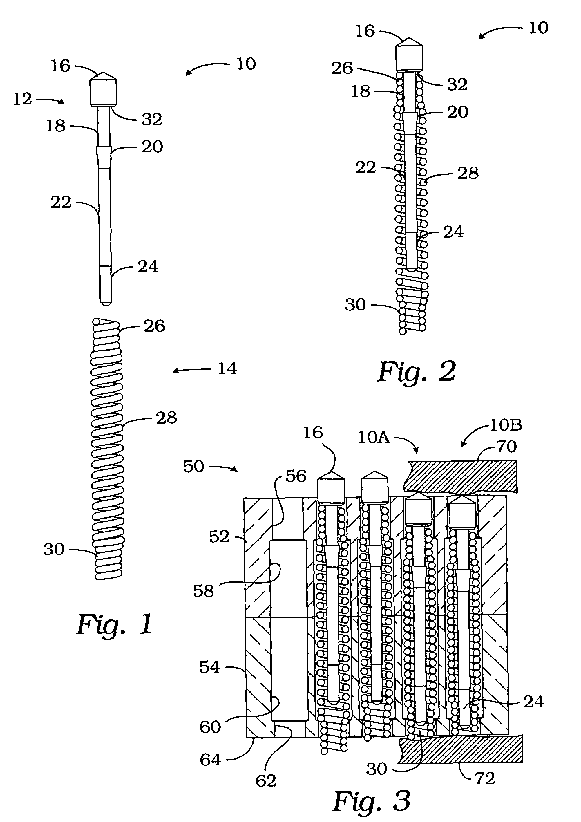
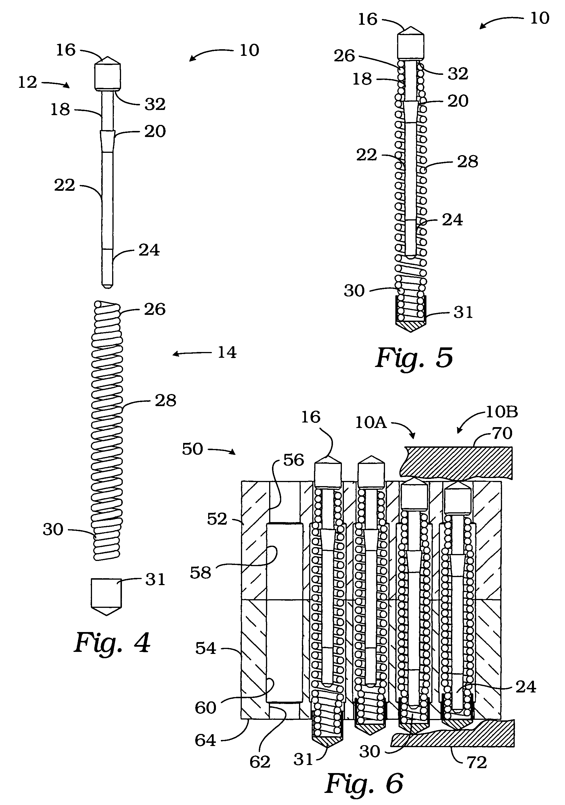
[0010]Referring to FIGS. 1 and 2, a contact spring probe of the present invention is generally indicated by reference numeral 10. Probe 10 includes a plunger 12 and a spring 14. Plunger 12 includes a tip 16, a shaft 18, a flange or shoulder 20, a body 22 and a tail 24. Plunger 12 may be fabricated by various methods such as machining from a single piece of conductive material such as beryllium copper or steel or the like and may be plated with gold or other material. The tip 16 illustrated is a 120° convex tip which is used to test plated through holes, pads and lands. The smooth cone shape allows plated through holes to be tested with minimal wetness marks to the device or unit under test. The point of the tip 16 is used to test pads and lands. Tip 16 is one example of many probe tips that may be used such as a spear point tip, a flat tip, a 60° chisel tip or an 8-point crown tip, for example. The particular tip configuration may be chosen as appropriate for a particular use or app...


PUM


Abstract

A contact spring probe includes a plunger and a spring with a pair of opposed closed coils separated by an open coil. The plunger is secured at one end to one set of closed coils with a shoulder, flange or barb extending from the body of the plunger.

Description

FIELD OF THE INVENTION[0001]This invention relates to contact spring probes and, more particularly, to a contact spring probe with a dual tapered spring and plunger retained by the spring.BACKGROUND OF THE INVENTION[0002]Contact spring probes are known in the art. The typical contact spring probe includes a barrel, a plunger and a spring which urges the plunger outwardly from the barrel. The spring and plunger are encapsulated by the barrel which is press-fit into a socket of a test fixture. The electrical conduction path from the probe tip to the socket is typically from the probe to the spring, to the barrel to the socket, or from the probe to the barrel to the socket. Long signal paths may reduce or degrade the electrical performance of the probe and may contribute to mechanical degradation or failure.SUMMARY OF THE INVENTION[0003]The present invention provides a contact spring probe with a dual tapered spring with closed coils at each end separated by open active coils, and a pl...

Claims


Application Information

Patent Timeline
IPC IPC(8): G01R31/02H01R13/24
CPCH01R13/2421G01R1/06722H01R2201/20G01R1/07314
Inventor MARX, DONALD A.THURSTON, WILLIAM E.
Owner INTERCONNECT DEVICES
Why Eureka
Try Eureka