Long-haul airplane

a long-haul airplane and flight deck technology, applied in the field of long-haul airplanes, can solve the problems of obliging pilots and requiring two flight crews for long-haul airplanes, and achieve the effect of preventing the floor from weakening

Active Publication Date: 2007-01-02
AIRBUS OPERATIONS (SAS)
View PDF34 Cites 28 Cited by
  • Summary
  • Abstract
  • Description
  • Claims
  • Application Information

AI Technical Summary

Benefits of technology

[0004]Thus, said pilots may pass directly from the flight deck into the private cabin, and vice versa, without passing through the passenger cabin. The present invention can therefore be used to isolate all the flight crews from the rest of the aircraft by geographically grouping the pilots' flight function and rest function together. Furthermore, the disposition of the private cabin according to the invention makes it possible to gain volume and seats in the commercial zone, this gain naturally being economically valuable for the airline operating the aircraft.
[0007]To allow the easy passage of said wall elements through said opening in the floor, the latter has an oblong shape, for example at least approximately rectangular. In addition, to prevent weakening the floor of the flight deck, said opening is advantageously transversal relative to the fuselage.
[0008]As a result it is advantageous that each of said individual elements be relatively flat and require only an opening of reduced dimensions for it to be inserted into said storage compartment.

Problems solved by technology

It is known that long-haul airplanes may require two flight crews when the distances they are traveling are particularly long.
As a general rule, such a rest cabin is disposed in a commercial zone, for example behind the cockpit or in the tail of the aircraft, which has the disadvantage of obliging the pilots to pass through the passenger cabin to go from the flight deck to the rest cabin and to return therefrom.

Method used


Image

  • Long-haul airplane
  • Long-haul airplane
  • Long-haul airplane

Examples


Embodiment Construction

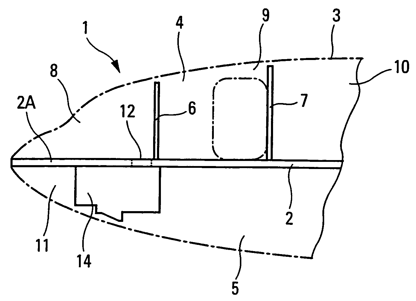
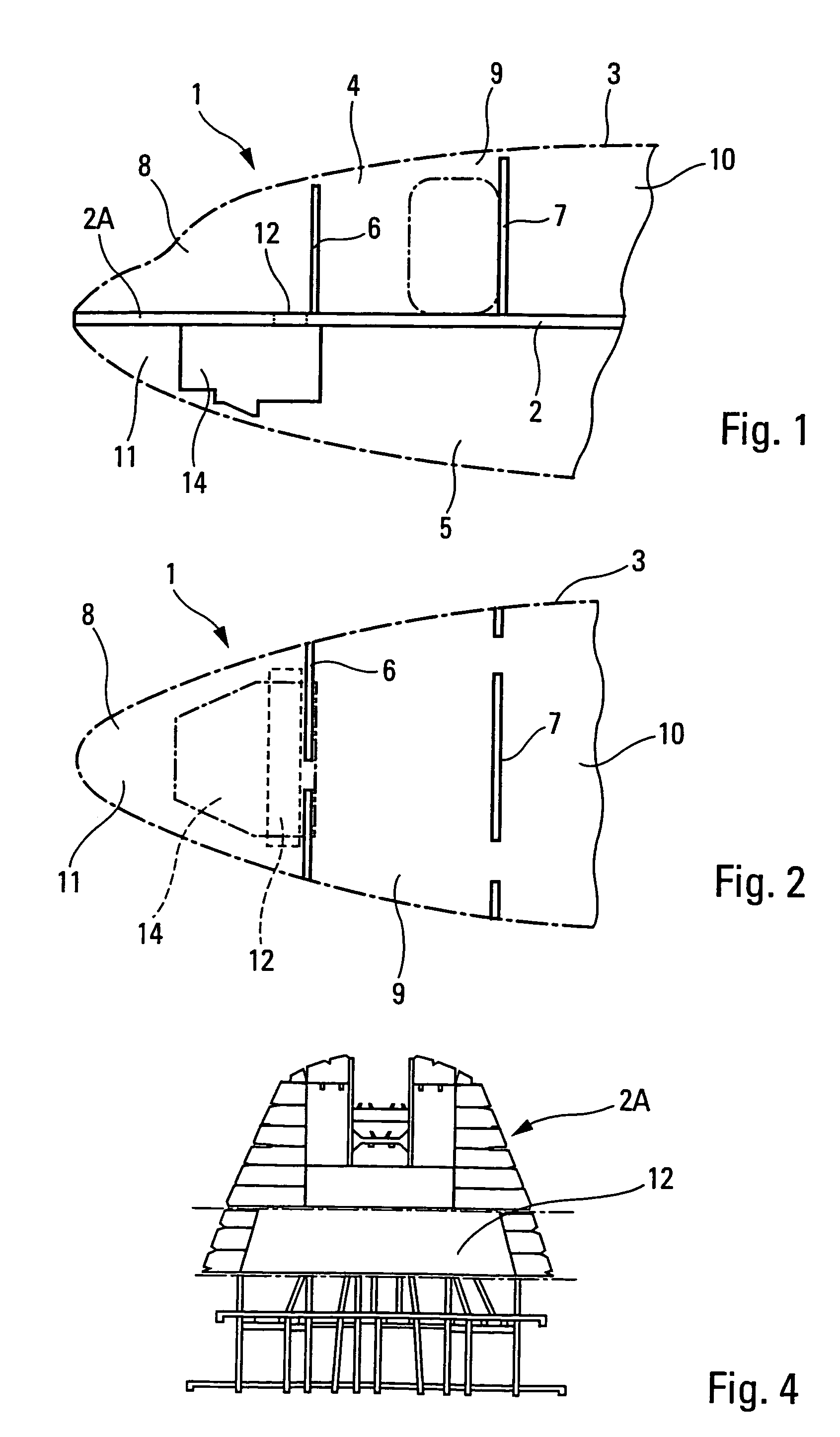
[0022]Schematic FIGS. 1 and 2 show the front 1 of a long-haul airplane. This shows the horizontal longitudinal floor 2 separating the fuselage 3 into an upper space 4 and a lower space 5. In the upper space 4 are arranged, with the aid of partitions 6, 7, the flight deck 8, an entrance 9 and the passenger cabin 10. In the lower space 5 are arranged storage compartments, indicating only the storage compartment 11 disposed beneath the flight deck 8 and separated from the latter by the front portion 2A of the floor 2 forming the floor of said flight deck 8.

[0023]In the vicinity of the partition 6, separating the flight deck 8 from the entrance 9, the floor 2A of the flight deck 8 comprises an opening 12 establishing a communication passage between the flight deck 8 and the storage compartment 11 through said floor 2A. As can be seen in FIGS. 2 and 4, said opening 12 is oblong and transversal relative to the fuselage 3.

[0024]According to the present invention, the long-haul airplane acc...


PUM


Abstract

A long-haul airplane has a private cabin for the pilots within a storage compartment disposed on a floor below the flight deck. The private cabin is in communication with the flight deck through an opening in the floor.

Description

BACKGROUND OF THE INVENTION[0001]It is known that long-haul airplanes may require two flight crews when the distances they are traveling are particularly long. It is therefore indispensable that they comprise a private rest cabin in which one of said crews—which comprises at least two pilots—may rest while the other crew flies the airplane. As a general rule, such a rest cabin is disposed in a commercial zone, for example behind the cockpit or in the tail of the aircraft, which has the disadvantage of obliging the pilots to pass through the passenger cabin to go from the flight deck to the rest cabin and to return therefrom. In addition, in such a disposition, said rest cabin occupies a portion of said commercial zone, so that a certain number of passenger seats, usually of the order of 6 to 8, are removed in consequence.[0002]The purpose of the present invention is to remedy these disadvantages.SUMMARY OF THE INVENTION[0003]For this purpose, according to the invention, the long-hau...

Claims


Application Information

Patent Timeline
Patent Type & Authority Patents(United States)
IPC IPC(8): B64D11/00
CPCB64C1/068B64D11/00B64D2011/0076B64D2011/0046B64C1/0683
Inventor GUERING, BERNARD
Owner AIRBUS OPERATIONS (SAS)
Why Eureka
Try Eureka