Wheel chair apparatus and method

a technology of wheel chairs and apparatuses, which is applied in the direction of wheelchairs/patient conveyances, transportation items, cycles, etc., can solve the problems of cumbersome installation and transportation, large space requirements for storage units, and substantial obstacles to mobility and everyday tasks, etc., to achieve the effect of reducing the space required for storage units, quick and easy, and improving traction

Inactive Publication Date: 2006-10-10
MIDAMERICA ELECTRONICS CORP
View PDF58 Cites 44 Cited by
  • Summary
  • Abstract
  • Description
  • Claims
  • Application Information

AI Technical Summary

Benefits of technology

[0021]The motor wheel has a relatively large diameter of eight and half inches. This permits easy passage over fairly large obstructions such as doorsills. The motor incorporates two large permanently lubricated sealed ball bearings. The wiring passes out through the center of one of the bearings, up under a protective cover to the electronic control box located above the motor
[0022]The unit overcomes restrictions of prior art of approaching a desk, a table, a bathroom sink, a water fountain and a myriad of other places by allowing the steering column to be released and rotated back in the operator's lap. From the locked upright position, the steering column can also be folded forward down against the floor and then turned to the side, providing complete open access for entering and leaving the wheel chair. There is a release knob, located near the front edge of the wheel chair seat, which provides easy access for moving the steering column. When the release knob is pulled, the motor control is automatically turned off. In order to allow this feature to be effective the motor control head at the top of the steering column must be very slim and small. With the unit disconnected from the wheel chair and the battery pack removed, the steering column can then be folded down over the top of the frame where it locks in a centered position. This minimizes the space required for storing the unit and also provides a handle for moving the folded unit.
[0023]The process of connecting and disconnecting the unit with the wheel chair is quick and easy, requiring no tools, allowing a handicapped person to fix the drive apparatus in place under the wheel chair for use.
[0024]There are two lightweight brackets bolted to the inside rear of the wheel chair frame with outward slanted guides. There are engagement seats for the driver apparatus formed on the inner surface of these brackets. A swing assembly or caster lever is hinged at the rear of the drive apparatus' frame. It rotates out approximately 45°. The swing assembly rotates over center and is held in the out position by the weight of the battery, and supported by two roller casters. The swing assembly supports a horizontal rectangular bar, which is transverse to the wheel chair and extends almost the full width of the inside of the wheel chair frame. The casters are mounted near the outer end of this horizontal bar. Mounted to the top of the battery handle is an inverted V Delrin®acetal resin slide. To connect the unit, the swing assembly must be in the out position, and the steering column turned at 90° (to act as a brake). The wheel chair is moved over the drive unit, and as the horizontal bar comes in contact with the slanted guides on the wheel chair brackets the roller casters allow the unit to be guided laterally until the rectangular bar is captured by the engagement seats on the wheel chair brackets. As the wheel chair moves further forward, the swing assembly is driven to an upright vertical position. It is held in this vertical position by a releasable latch mechanism. As the swing assembly is driven to the upright vertical position, the rear of the frame is lifted which pushes the inverted V Delrin®acetal resin slide against the bottom of the X-frame of the wheel chair. This lifts the front of the wheel chair and at the same time the roller casters are lifted off the ground. With the front of the wheel chair lifted, needed weight is added to the motor wheel providing better traction.
[0025]A second means of connecting the unit can be accomplished by applying the brakes on the wheel chair. The drive apparatus can then be backed under the wheel chair using the power of the drive unit. This design results in a three-wheeled device with a very short wheelbase. Since the front casters of the wheel chair are only slightly lifted off the ground, they serve as outriggers and prevent the unit from tipping.

Problems solved by technology

Substantial obstacles to mobility and everyday tasks of living continue for those disabled and bound to wheel chairs.
These devices are cumbersome in their operation, installation and transportation.
This creates difficulty in packing, as for example in the trunk of an automobile.
Weight represents a substantial hardship, particularly for the elderly person, whose caregiver is commonly an elderly spouse.
Prior art devices are also bulky and do not collapse into a small enough package for convenient transportation, again as in the trunk of a car.
The prior art units do not have batteries that are easily removable.
This shaft is not movable, and accordingly obstructs ingress and egress from the wheel chair.
The unadjustable vertical control shaft makes simple tasks difficult, such as pulling the chair up to the table, as for reading or a meal.
These units are also difficult to install for a caregiver.
They are prohibitively difficult for the disabled individual themselves to install.
This is due to the mounting apparatus, which cannot automatically seat itself by simple engagement with the chair, which has no alignment guides to ease installment and which also prevents folding the chair up for storage when the apparatus is attached.
The prior art devices have inefficient drive trains that use drive chains and further necessitate inefficient gearing and small drive wheels.
Their systems are only 35% efficient.
This inefficiency leads to a choice between either large, heavy batteries or smaller batteries that use an inordinate amount of power with an appreciably shorter charge life.
In operation, the prior art units use small drive wheels that too readily transfer shock from minor impediments, such as a brick floor.
Even slightly larger objects, such as a cobble stone street, become virtually impossible to traverse.

Method used


Image

  • Wheel chair apparatus and method
  • Wheel chair apparatus and method
  • Wheel chair apparatus and method

Examples


Embodiment Construction

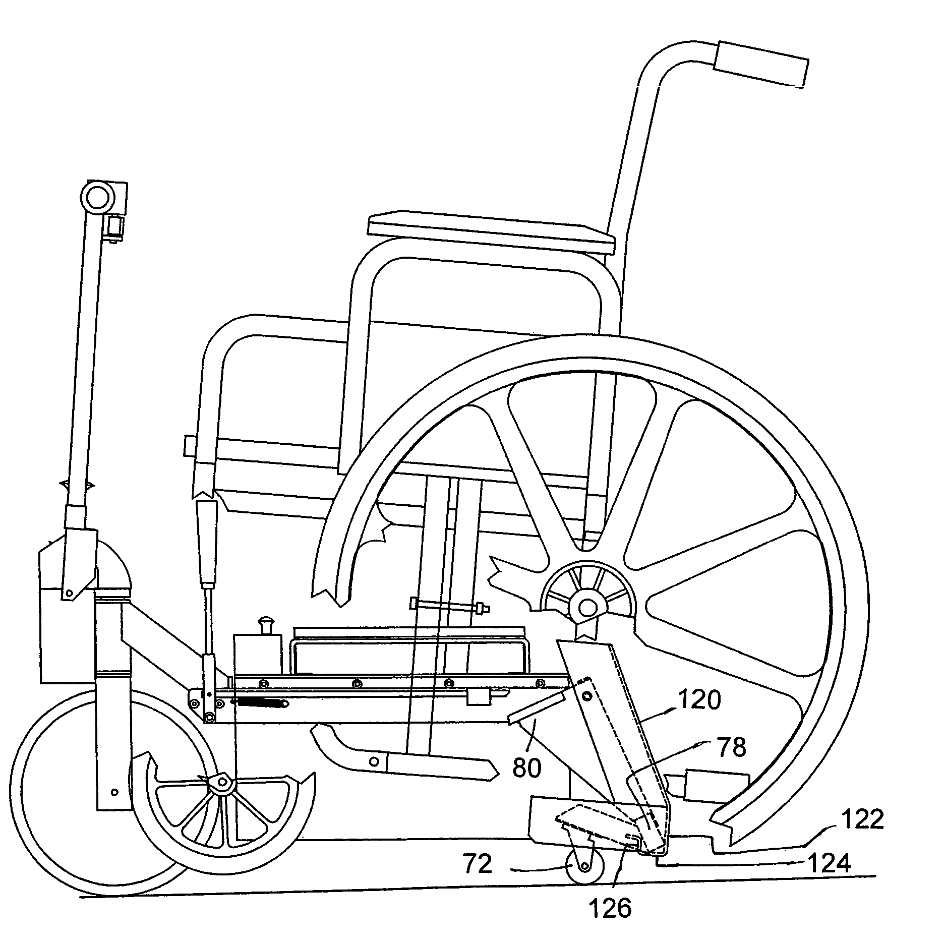
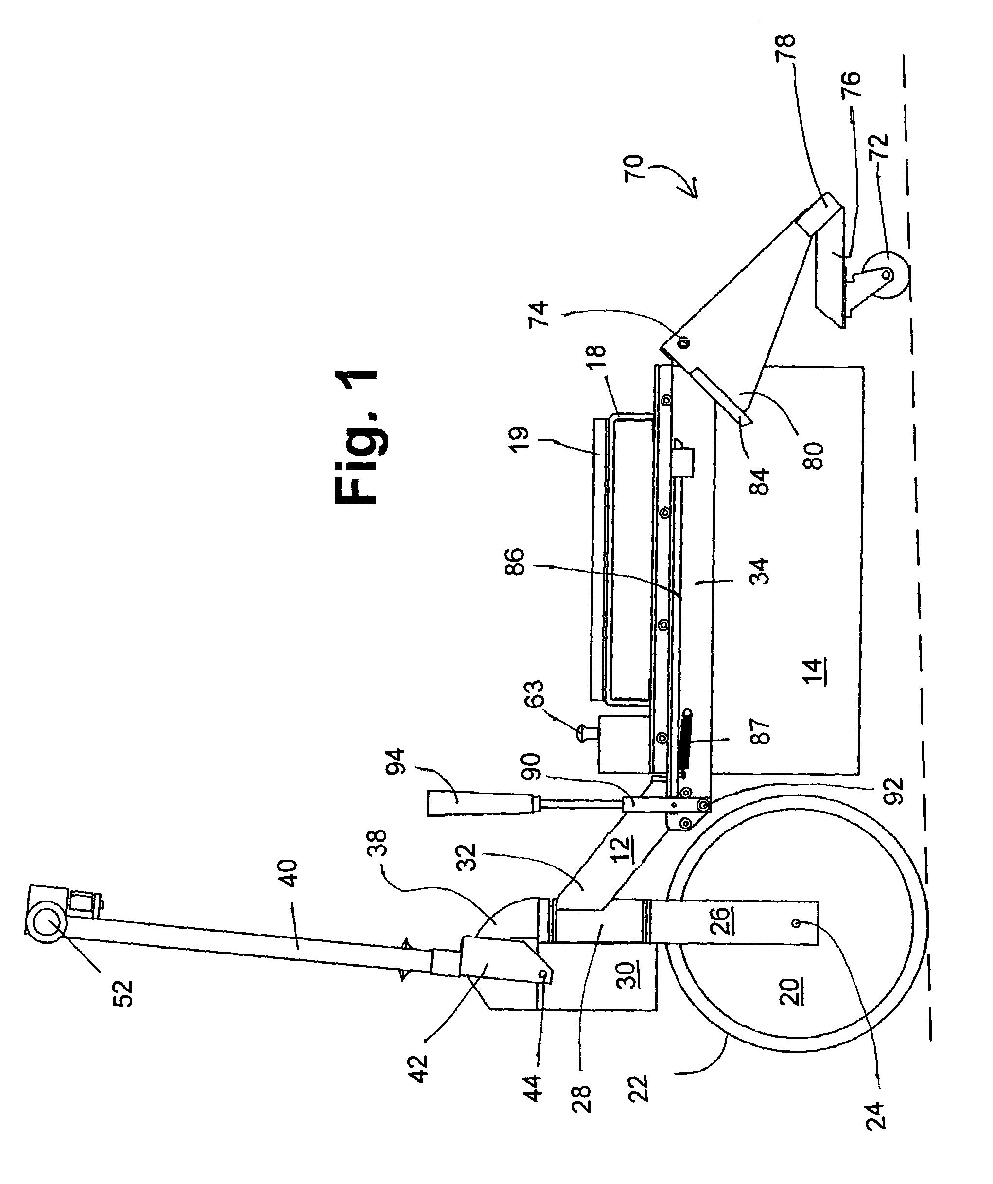
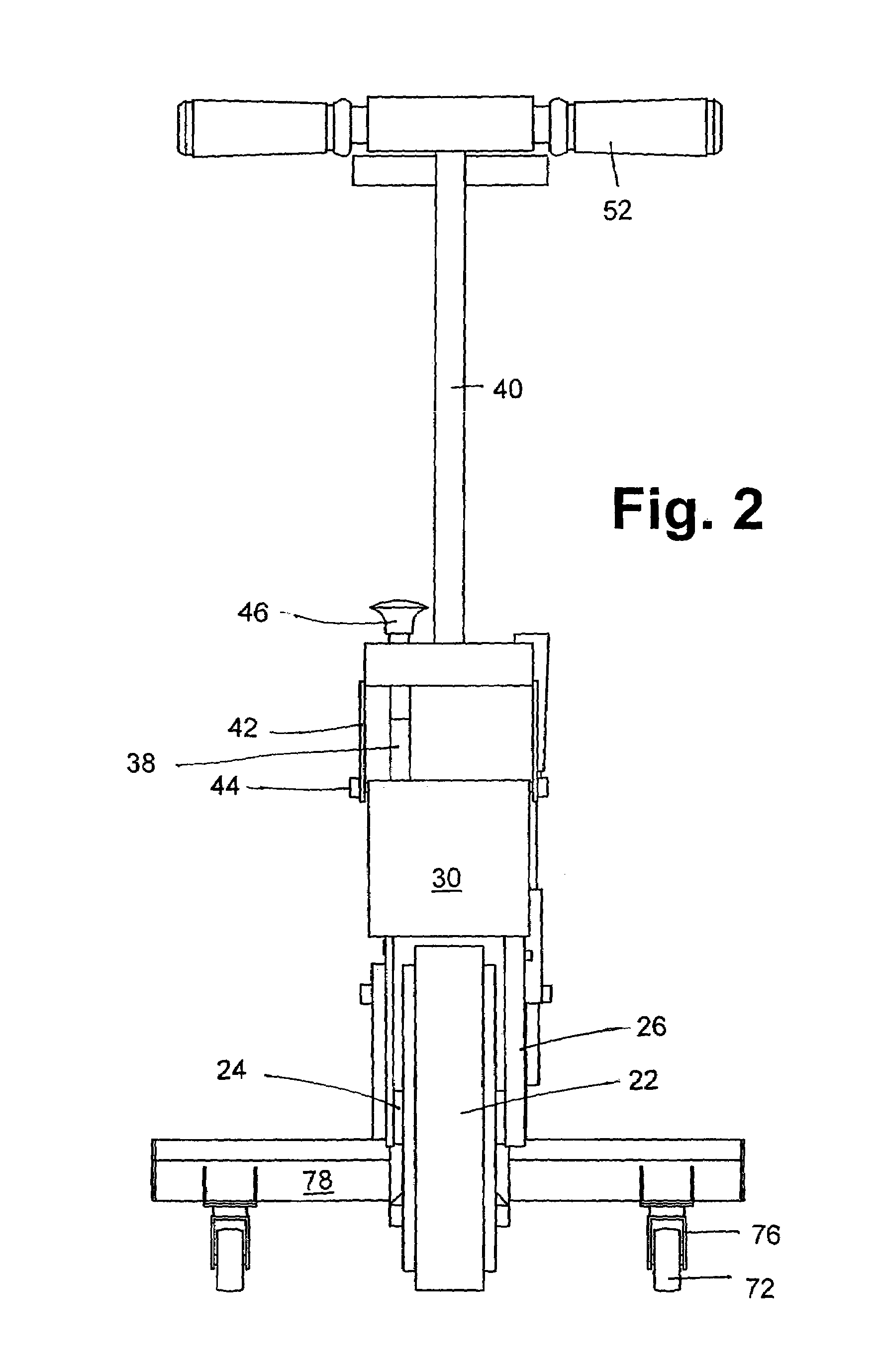
[0046]Referring to the accompanying drawings in which like reference numbers indicate like elements, FIGS. 1, 2, 3, 4 and 5 are side, front, side and top views, respectively, of the wheel chair motor drive of the present invention. FIG. 15 shows the motor drive apparatus 10 engaged with a wheel chair.

[0047]The wheel chair motor drive apparatus 10 is comprised of a frame 12 and, when assembled, a battery housing 14.

[0048]Drive wheel 20 comprises the housing for a high torque electric motor (not shown) within the wheel in the depicted embodiment. The wheel 20 is also the rotor of the electric motor, as well as the casing for the stator housed within it. The motor and wheel 20 are coaxial in the depicted embodiment. The wheel 20 also has a friction surface or tread 22 disposed circumferentially thereon.

[0049]The drive wheel axle 24 supports drive wheel forks 26. The forks 26 are fixedly attached to a fork bearing journal 28 which is substantially vertical in the depicted embodiment.

[00...


PUM


Abstract

A wheel chair drive apparatus includes a frame having a wheel mount, a battery mount, and a control shaft mount. A drive wheel has a drive motor incorporated within the drive wheel. A battery is in operative communication with the drive motor via a detachable jack. A battery housing is dimensioned to mount in the battery mount of the frame and has a handle. A control shaft pivotably mounted on the control shaft mount, so that it has a stow position, and operating position, a user entry position and a table use position. A caster lever is pivotably mounted to the frame, so that it has a rolling position and an engaged position. The caster lever is disposed to engage a receiving seat on a wheel chair. A locking lever is releasably biased toward a position locking the caster lever in the engaged position.

Description

CROSS-REFERENCE TO RELATED APPLICATIONS[0001]None.STATEMENT REGARDING FEDERALLY SPONSORED RESEARCH OR DEVELOPMENT[0002]Not Applicable.APPENDIX[0003]Not Applicable.BACKGROUND OF THE INVENTION[0004]1. Field of the Invention[0005]The present invention is in the field of motorized wheel chairs, particularly, separable apparatuses attachable to standard wheel chairs to provide power to drive them.[0006]2. Related Art[0007]Substantial obstacles to mobility and everyday tasks of living continue for those disabled and bound to wheel chairs. There is a continuing need to make mobility for the wheel chair bound more reliable and convenient.[0008]Motor drives for standard wheel chairs exist in the prior art. U.S. Pat. No. 5,494,126 to Meeker and U.S. Pat. No. 5,050,695 to Kleinwolterink Jr. describe motor drive units that may be attached to standard push wheel chairs.[0009]U.S. Pat. No. 5,050,695 describes a geared brush type DC motor chain coupled to a very small drive wheel. It makes use of ...

Claims


Application Information

Patent Timeline
Patent Type & Authority Patents(United States)
IPC IPC(8): A61G5/04B62D61/12A61G5/10B62D1/00H02P7/288
CPCA61G5/047A61G5/10A61G2005/1051A61G5/1051
Inventor KIDD, WILLIAM W.JENKINS, JOHN P.
Owner MIDAMERICA ELECTRONICS CORP
Why Eureka
Try Eureka