Antenna device

a technology of antenna coil and antenna coil, which is applied in the direction of loop antennas with ferromagnetic cores, resonant antennas, instruments, etc., can solve the problems of difficult magnetic fluxes entering the mobile phone, low radiation efficiency of magnetic fluxes transmitted through the antenna coil, and significant weak current in the antenna coil. , to achieve the effect of reducing the thickness and favorable communication with a reader/writer

Active Publication Date: 2009-04-16
MURATA MFG CO LTD
View PDF6 Cites 50 Cited by
  • Summary
  • Abstract
  • Description
  • Claims
  • Application Information

AI Technical Summary

Benefits of technology

[0009]To overcome the problems described above, preferred embodiments of the present invention provide antenna devices that can be surface-mounted on a circu

Problems solved by technology

However, since a lateral area of the magnetic core is relatively small in Japanese Unexamined Patent Application Publication No. 2004-153463, the radiation efficiency of the magnetic fluxes transmitted through the antenna coil is relatively low.
Accordingly, it is difficult for the magnetic fluxes to enter the mobile phone and the current caused in the antenna coil is significantly weak.
Accordingly, there is a problem in that the optimum antenna sensitivity cannot be achieved.
However, since the antenna coil described in Japanese Unexamined Patent Application Publication No. 2006-050522 is configured to receive the magnetic fluxes at the ends thereof, the current induced in the antenna coil by the incoming magnetic fluxes is relatively weak when the central portion is placed over the reader/writer.
That is, the possibility of successful communication with automat

Method used


Image

  • Antenna device
  • Antenna device
  • Antenna device

Examples


Embodiment Construction

[0038]Preferred embodiments of the present invention will be described below with reference to the drawings.

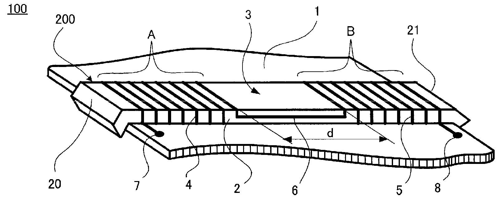
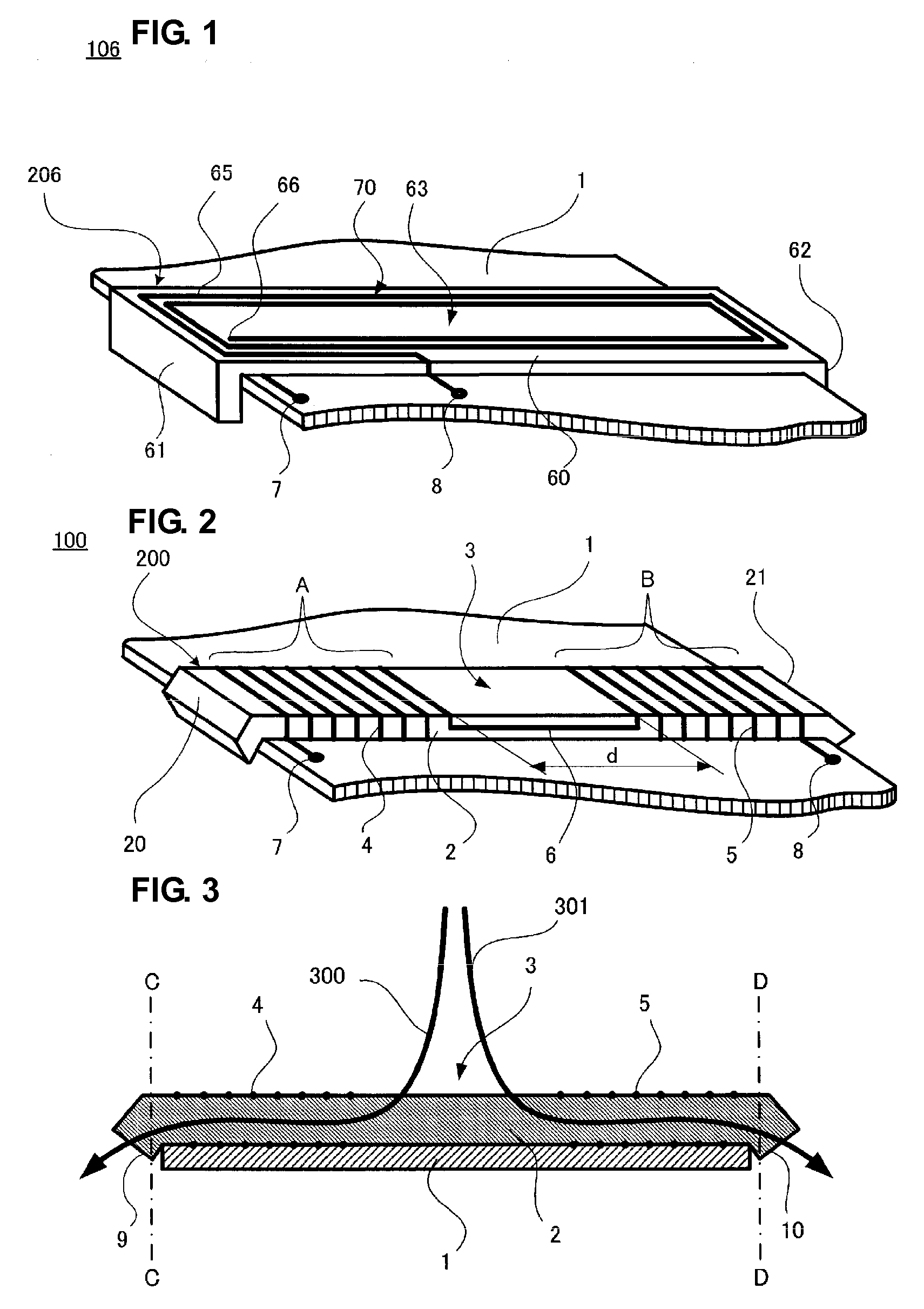
[0039]A first preferred embodiment will be described with reference to FIG. 1. FIG. 1 is a perspective view of an antenna device 106 that is a first preferred embodiment of the present invention.

[0040]An antenna coil 206 is provided on a principal surface of a circuit substrate 1. The antenna coil 206 can preferably be readily adhered to the circuit substrate 1 using an adhesive or a double-sided adhesive tape, for example. The circuit substrate 1 preferably is a substrate provided in a mobile phone. An RF circuit and a control circuit, not shown, are provided on the circuit substrate 1. The circuit substrate 1 is arranged in a casing to be substantially parallel to a principal surface of the mobile phone terminal. In addition, a ground electrode (not shown) is provided on substantially the entire surface of the circuit substrate 1 that faces a surface on which the antenna coi...


PUM


Abstract

An antenna device having a magnetic core to be surface-mounted on a circuit substrate includes a pair of coil portions spaced apart from each other at a predetermined interval. The coil portions are connected by a connecting conductor. An end of the magnetic core includes a curved or bent portion curved toward the circuit substrate. This structure defines an RFID antenna device having an improved receiving sensitivity that can be surface-mounted without increasing the thickness of a casing of a mobile electronic device.

Description

BACKGROUND OF THE INVENTION[0001]The present invention relates to antenna devices that can be utilized as an antenna in mobile electronic devices, for example.DESCRIPTION OF THE RELATED ART[0002]As disclosed in, for example, Japanese Unexamined Patent Application Publication No. 2004-153463 and Japanese Unexamined Patent Application Publication No. 2006-050522, antenna coils are mounted in casings of mobile electronic devices, such as mobile phones, that are equipped with RFID (Radio Frequency Identification) radio tags communicating with external devices via electromagnetic signals.[0003]According to Japanese Unexamined Patent Application Publication No. 2004-153463, data carrier signals from the outside are received by an antenna coil mounted on a substrate included in a mobile phone so as to transmit and receive data in a non-contact manner to and from a reader / writer. The antenna coil of Japanese Unexamined Patent Application Publication No. 2004-153463 is a substantially planar...

Claims


Application Information

Patent Timeline
IPC IPC(8): H01Q7/06
CPCG06K19/07749H01Q1/2225H01Q7/06H01Q1/526H01Q1/243H01Q7/08H01Q1/24G06K19/00
Inventor ITO, HIROMITSUKUBO, HIROYUKIYOSUI, KUNIAKI
Owner MURATA MFG CO LTD
Why Eureka
Try Eureka