Embedded toroidal inductor

a toroidal inductor and embedded technology, applied in the field of toroidal inductors, can solve the problems of not substantially containing the difficulty of implementing toroidal inductors, and the inability to substantially contain the magnetic field of the planar spiral inductors, etc., and achieve the effect of increasing the relative permeability

Active Publication Date: 2007-01-02
HARRIS CORP
View PDF21 Cites 30 Cited by
  • Summary
  • Abstract
  • Description
  • Claims
  • Application Information

AI Technical Summary

Problems solved by technology

In miniature RF circuitry, however, implementation of toroidal inductors is particularly difficult.
Planar spiral inductors suffer from a serious drawback in that, in contrast to a toroidal inductor, they do not substantially contain the magnetic field that they produce.
While surface mount toroidal inductors work well, the circuit board real estate required for such components is a significant factor contributing to the overall size of RF systems.
These additional steps naturally involve further expense.
Also, such techniques are poorly suited for use with other types of substrates, such as ceramic types described below.
Typically, the range of commercially available LTCC materials have been fairly limited.

Method used


Image

  • Embedded toroidal inductor
  • Embedded toroidal inductor
  • Embedded toroidal inductor

Examples


Embodiment Construction

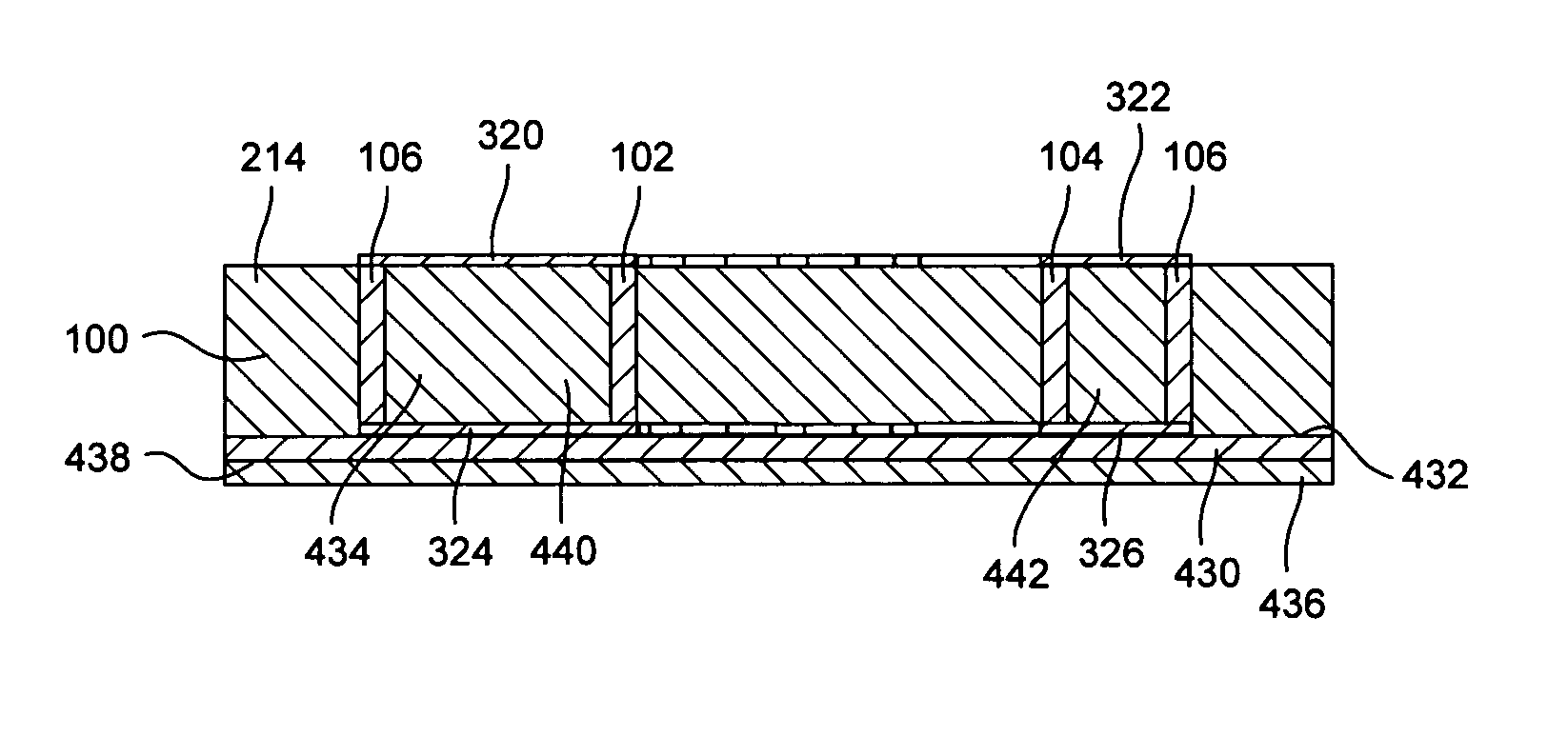
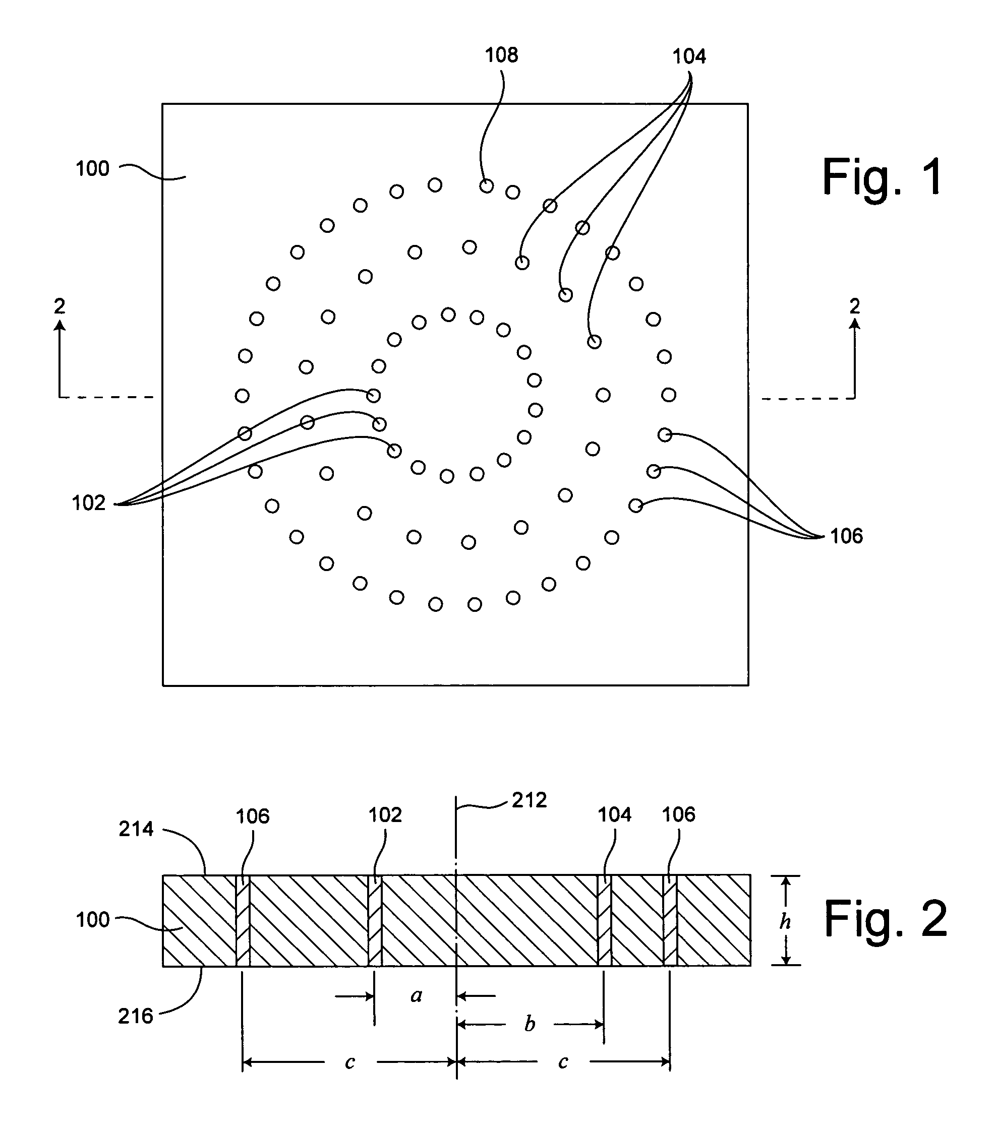
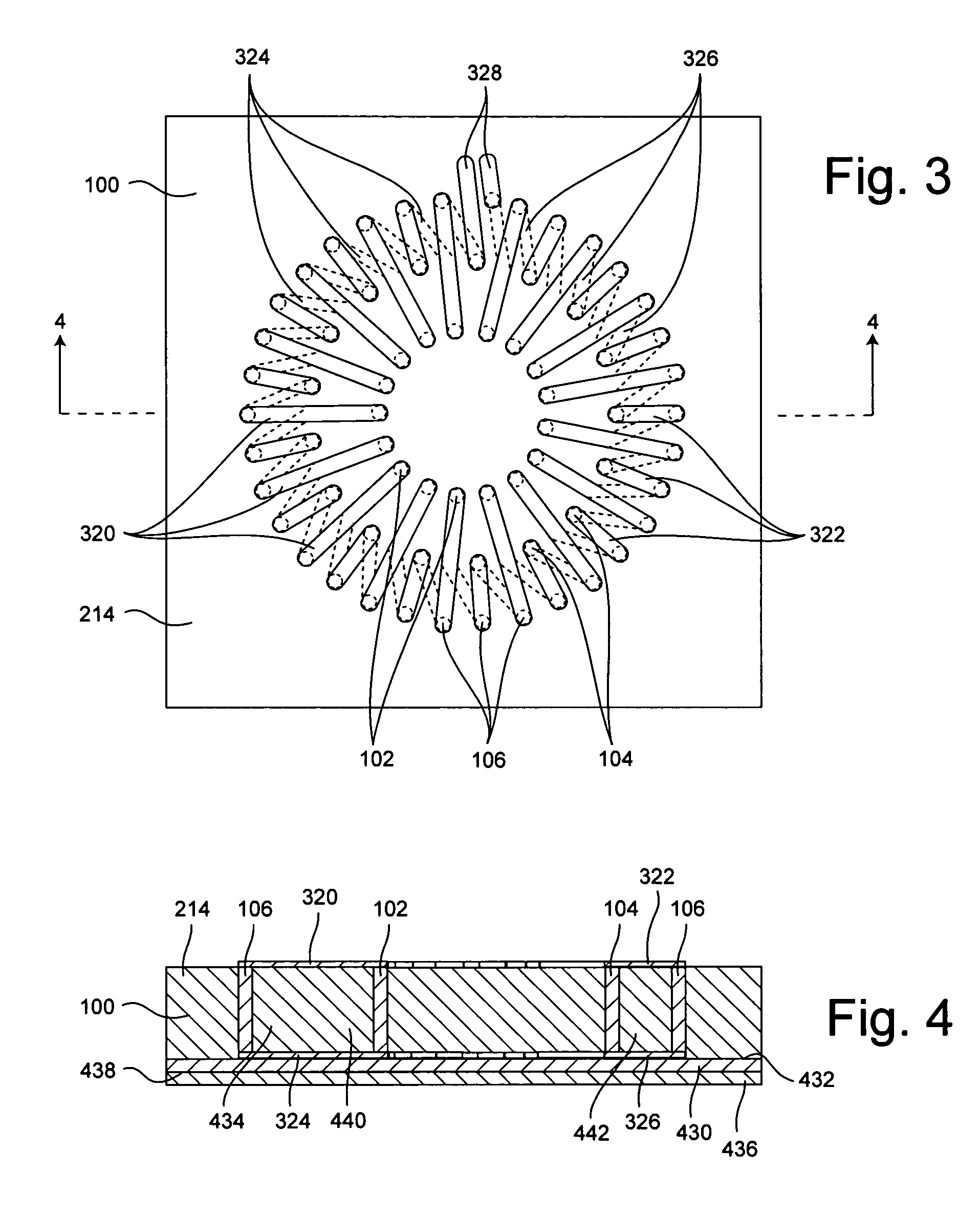
[0035]The invention relates to a toroidal inductor integrated within a substrate and a method of making same. As defined herein, a toroidal inductor is an inductor having windings that define a closed path to substantially contain flux generated by the inductor. As such, the region defined by the inductor windings is not limited to a donut-shape, but also can be disk-shaped, or have any other shape suitable for defining a closed path for substantially containing the magnetic flux generated by the inductor.

[0036]The method shall be described in reference to FIGS. 1–2, and the flowchart in FIG. 15. The method can begin with step 1502 by forming a suitably sized substrate layer 100. The substrate layer 100 can be formed from any suitable substrate material and can include any number of sub-layers as appropriate to obtain a desired substrate thickness. For example, the substrate layer 100 can include one or more layers of unfired ceramic tape. The ceramic tape can be any of a variety of...


PUM

PropertyMeasurementUnit
distanceaaaaaaaaaa
electrical characteristicaaaaaaaaaa
temperatureaaaaaaaaaa

Abstract

A toroidal inductor, including a substrate (100), a toroidal core region (434) defined within the substrate, and a toroidal coil including a first plurality of turns formed about the toroidal core region and a second plurality of turns formed about the toroidal core region. The second plurality of turns can define a cross sectional area (440) greater than a cross sectional area (442) defined by the first plurality of turns. The substrate and the toroidal coil can be formed in a co-firing process to form an integral substrate structure with the toroidal coil at least partially embedded therein. The first and second plurality of turns can be disposed in alternating succession. The toroidal core region can be formed of a substrate material having a permeability greater than at least one other portion of the substrate.

Description

BACKGROUND OF THE INVENTION[0001]1. Statement of the Technical Field[0002]The inventive arrangements relate generally to inductors and more particularly to toroidal inductors.[0003]2. Description of the Related Art[0004]As is well known, a magnetic field is generated each time an electric current is present in a conductor. An inductor is a passive electrical component that includes a series of conductive windings or coils (hereinafter “turns”) which cooperate to define the magnetic field in a specified region when an electric current is established in the turns. The ability of an inductor to store energy in the magnetic field is described by an inductance L, which is generally proportional to the square of the number of turns N2 and the permeability μ of the regions in which the magnetic field is established. The permeability μ oftentimes is discussed in terms of relative permeability μr, which is the ratio of the permeability ∞ to the permeability of free space μ0. i.e.[0005]μr=μμ0...

Claims


Application Information

Patent Timeline
Patent Type & Authority Patents(United States)
IPC IPC(8): H01F5/00H01F27/28
CPCH01F17/0033H01F41/046Y10T29/4902H01F2027/2814
Inventor PLESKACH, MICHAEL D.THOMSON, ANDREW J.PAYAN, BAYARDO A.PROVO, TERRY
Owner HARRIS CORP
Why Eureka
Try Eureka