Detection of broadcast signals for defining useable frequency bands for powerline communication

a technology of broadcast signals and frequency bands, applied in the field of detection of broadcast signals for defining useable frequency bands for powerline communication, can solve the problems of emitted electro-magnetic signals, limiting the achievable data rate, and a lot of nois

Active Publication Date: 2007-01-02
SONY DEUT GMBH
View PDF6 Cites 24 Cited by
  • Summary
  • Abstract
  • Description
  • Claims
  • Application Information

AI Technical Summary

Benefits of technology

[0023]Broadcast RF signals which can be received by a wireless RF receiver in the environment of the PLC system can automatically be detected by the PLC system without needing any communication link between the wireless RF receiver and the PLC system. With this technology, the entire frequency range which is needed for powerline communication can be screened without interrupting running powerline communication sessions.

Problems solved by technology

Known PLC systems face a major problem in emitting electro-magnetic signals to the environment that disturb the reception of broadcast radio signals within the same frequency band.
A conventional power cable which is used for conveying PLC signals emits through its non-shielded sections generates some noise that could potentially disturb the reception of AM and Digital Radio Mondiale (DRM) broadcast signals by wireless receivers located in the same area.
Furthermore, restrictions imposed on the use of various frequency bands in the power line spectrum limit the achievable data rates.
In general, PLC systems emit so much noise on a wide frequency spectrum that receiving SW radio is limited within an area close to the PLC modem.
There are concerns that electro-magnetic emissions generated by PLC systems might result in a significant quality degradation of wireless services.

Method used


Image

  • Detection of broadcast signals for defining useable frequency bands for powerline communication
  • Detection of broadcast signals for defining useable frequency bands for powerline communication
  • Detection of broadcast signals for defining useable frequency bands for powerline communication

Examples


Embodiment Construction

[0033]In the following, one embodiment of the present invention as depicted in FIGS. 5 to 6b shall be explained in detail. The meaning of the symbols designated with reference numerals and signs in FIGS. 1 to 6b can be taken from an annexed table.

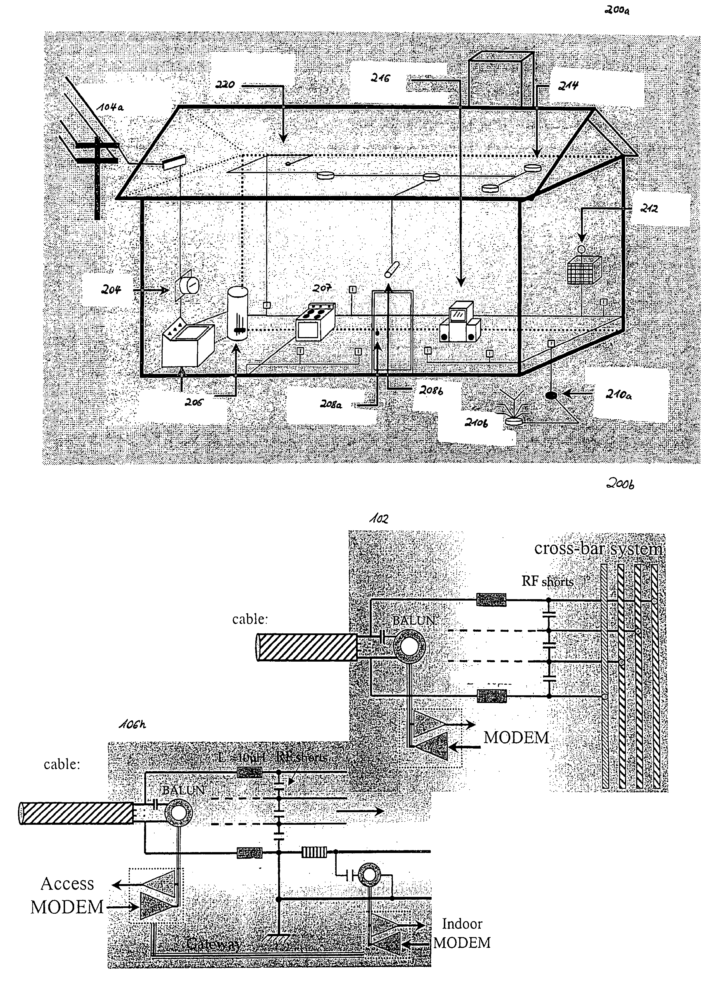
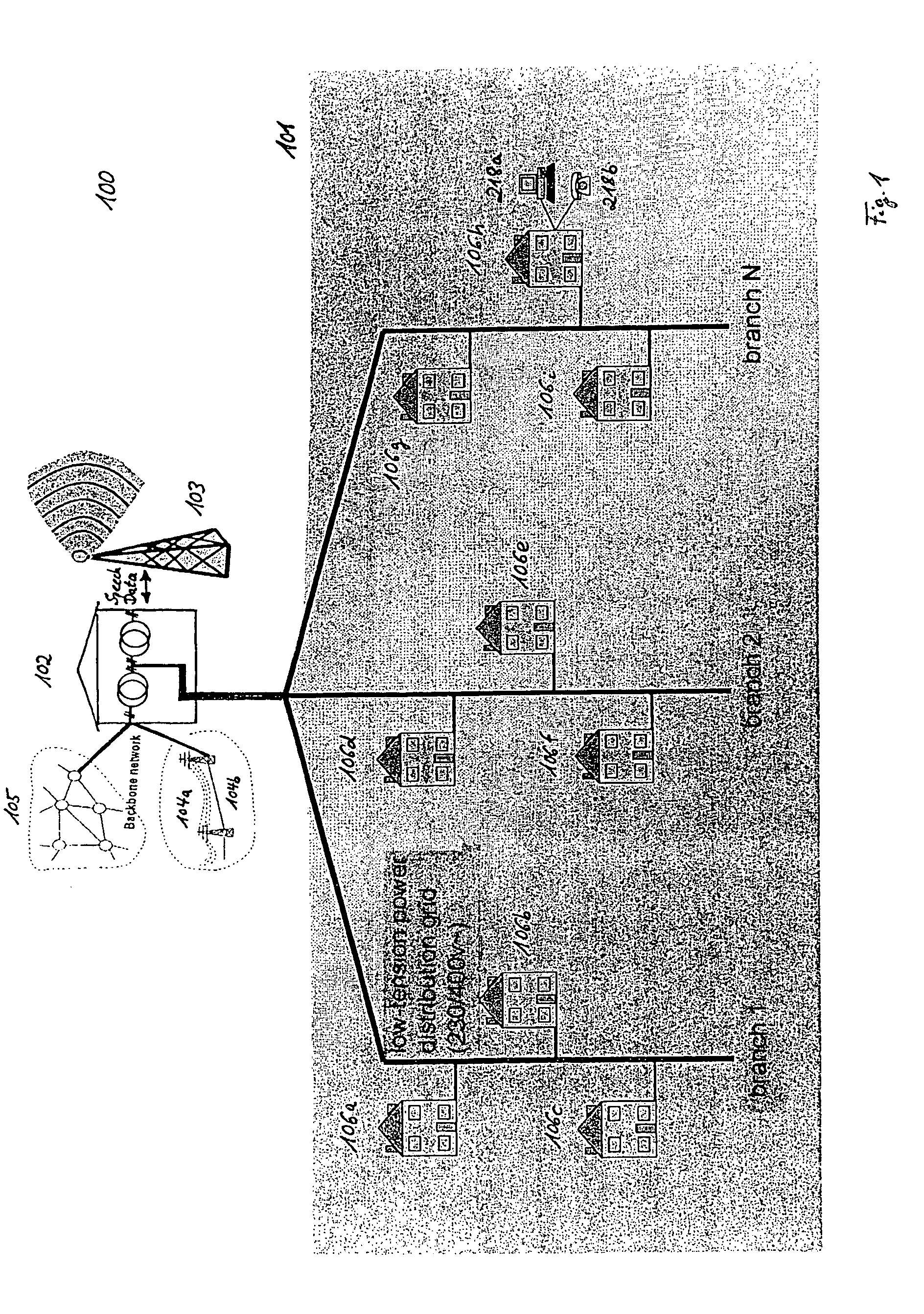
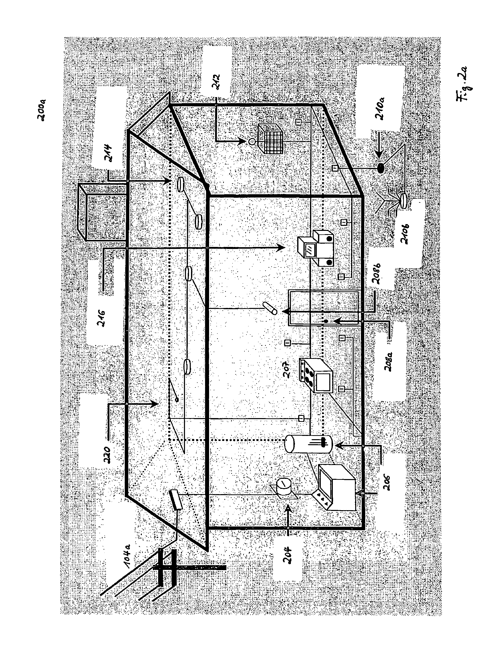
[0034]According to one embodiment of the present invention, every node 302, 306 participating in a powerline communication session uses its receiving device and the PLC cable as a detector for checking / listening whether there are receivable broadcast signals in the environment of the respective node (302 or 306) that should not be interfered by electromagnetic emissions generated by PLC signals (s(t)) transmitted via power supply lines of the PLC system 101 and which frequency bands have to be omitted during powerline communication. As depicted in FIG. 5, the detection of existing broadcast signals can be optionally or additonally performed in two phases:[0035]1. Initial scan: An initial scan of the entire applicable frequency band is used ...


PUM


Abstract

The present invention refers to a method for defining useable frequency bands for a powerline communication (PLC) system (101) using power supply lines of a power supply network (104a) for interconnecting a number of PLC nodes (302, 306) such that electromagnetic emissions generated by PLC signals (s(t)) transmitted via said power supply lines do not interfere with broadcast RF signals radiated in the same frequency bands. Before starting own communication activities, PLC nodes (302, 306) participating in a PLC session scan (S1a) the entire frequency range designated for powerline communication to detect (S1b) frequency bands which are occupied by broadcast services. During powerline communication the occurrence of broadcast signals is regularly checked (S2) by screening (S2a) the entire frequency range designated for powerline communication and detecting (S2b) relevant broadcast bands that should be omitted during powerline communication to avoid interference noise (n(t)). After that, new frequency bands for powerline communication are allocated (S3) within said frequency range, provided that these new bands are not occupied by any detected wireless service.

Description

FIELD AND BACKGROUND OF THE INVENTION[0001]The present invention generally relates to the field of powerline communication (PLC) systems. It particularly refers to a method for defining useable frequency bands for a PLC system using AC or DC (car appliances etc.) power supply lines of a power supply network interconnecting a number of PLC nodes such that electromagnetic emissions generated by PLC signals transmitted via said power supply lines do not interfere with broadcast RF signals radiated in the same frequency bands.[0002]According to the PLC technology power supply lines are used as a transmission channel for data (cf. FIG. 1). Powerline communications offers end users a broad spectrum of applications and services, which inter alia includes broadband Internet access, voice-over-IP (VoIP), multimedia services, home automation and energy management.[0003]The traditional arena for powerline solutions is home automation, which encompasses applications where simple on / off or state...

Claims


Application Information

Patent Timeline
Patent Type & Authority Patents(United States)
IPC IPC(8): G05B11/01H04J1/12H04B3/54H04M11/04
CPCH04B3/54H04B2203/5495
Inventor SCHWAGER, ANDREASBUCHNER, PETERZUMKELLER, MARKUSSTADELMEIER, LOTHAR
Owner SONY DEUT GMBH
Why Eureka
Try Eureka