Low cost method of producing radio frequency identification tags with straps without antenna patterning

a radio frequency identification and strap technology, applied in the direction of burglar alarm mechanical actuation, burglar alarm by hand-held articles removal, instruments, etc., can solve the problems of low cost, insufficient resolution of conventional patterning, etching and printing methods, and inability to provide the engineered performance of the device, etc., to achieve the effect of low cos

Active Publication Date: 2007-01-02
AVERY DENNISON CORP
View PDF29 Cites 80 Cited by
  • Summary
  • Abstract
  • Description
  • Claims
  • Application Information

AI Technical Summary

Benefits of technology

[0017]According to an aspect of the present invention, an RFID device is produced by a low cost method of manufacture utilizing conventional roll-to-roll manufacturing technology. Specifically, the present invention provides a method of making an RFID device from a web material including a conductive layer having one or more apertures and a continuous dielectric layer. The method comprises the steps of providing a web material including a continuous conductive layer and a continuous dielectric layer, forming at least one crease portion in the web material, the crease portion including a central portion of overlapped web material between adjacent portions of single ply web material, forming an aperture in the conductive layer by removing at least part of the central portion of the at least one crease portion; and applying at least one strap across the crease portion. The aperture aids in creating suitable coupling points for the strap to the antenna.

Problems solved by technology

Structures for these purposes can add complexity, thickness and inflexibility to the RFID device.
Conventional patterning, etching and printing methods may not provide adequate resolution, line / space separation or other qualities necessary to deliver engineered performance.
In addition, methods of manufacturing RFID devices that include combining a web of RFID chips or straps with a web of formed or printed RFID antennas are complicated by the need to account for any differences in the pitch of each web, or spacing between adjacent element on each web, so that the RFID chips or straps and antennas are aligned.
Moreover, while RFID tags and labels are inexpensive, and costs of RFID devices have been going down, the size and cost of such devices may make them impractical for use with small or inexpensive items.

Method used


Image

  • Low cost method of producing radio frequency identification tags with straps without antenna patterning
  • Low cost method of producing radio frequency identification tags with straps without antenna patterning
  • Low cost method of producing radio frequency identification tags with straps without antenna patterning

Examples


Embodiment Construction

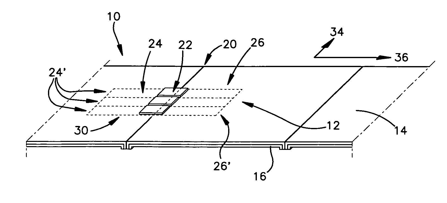
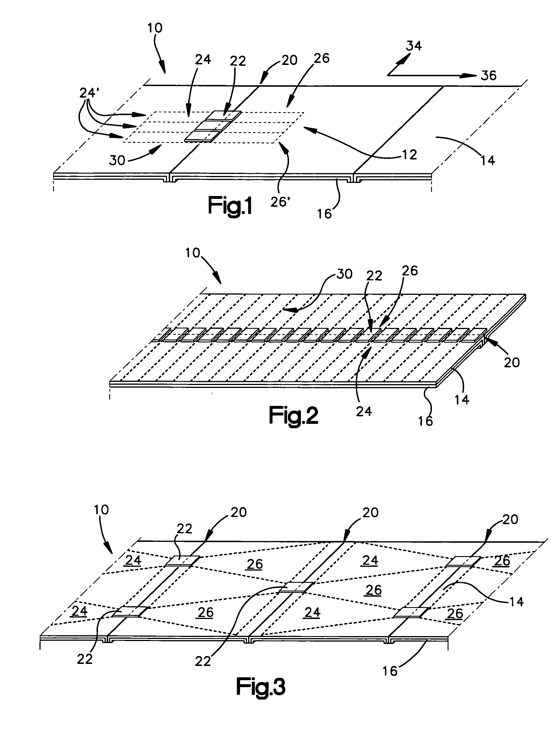
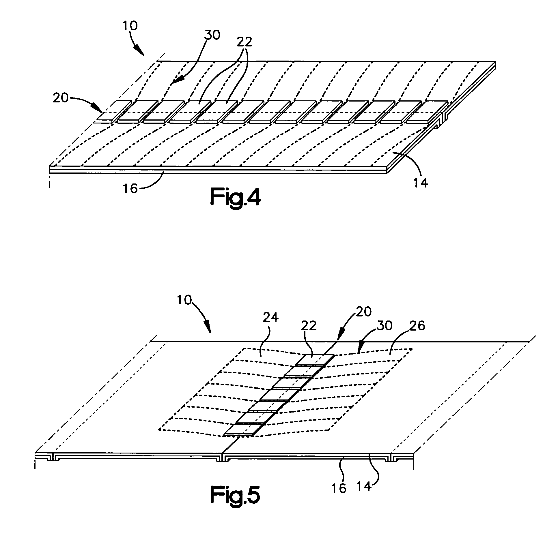
[0062]A web of radio frequency identification (RFID) devices includes a conductive layer atop an insulating layer, the conductive layer having one or more apertures therein. RFID chips or straps are electrically coupled to portions of the conductive layer on either side of one or more apertures, for use as antennas when the RFID devices are separated from one another, as by cutting.

[0063]The apertures may be formed by folding or creasing portions of the web, and removing parts of the folded or creased portion as set forth herein. The apertures may also be formed by a selective masking and evaporation process, or by any other suitable means. There may be a single aperture in a longitudinal direction of the web, or multiple apertures in a longitudinal or transverse direction of the web. The apertures may fully separate the conductive material on either side, or alternatively may only partially separate the conductive material, leaving one or more conductive bridges linking the conduct...


PUM

PropertyMeasurementUnit
thicknessaaaaaaaaaa
conductiveaaaaaaaaaa
dielectricaaaaaaaaaa

Abstract

A web of radio frequency identification (RFID) devices includes a conductive layer atop an insulating layer, the conductive layer having one or more apertures therein. Alternatively, the web may not include an insulating layer. RFID chips or straps are electrically coupled to portions of the conductive layer on either side of an aperture, for use as antennas when the RFID devices are separated from one another, as by cutting. The apertures may be formed by creasing portions of the web, and removing parts of the creased portion. There may be one or more apertures in a longitudinal or transverse direction of the web. The antenna shapes of various of the RFID devices may be tessellated, nesting within one another or having the same boundary, thereby improving efficiency by using substantially all of the conductive material. The RFID devices may be tested and / or programmed while remaining in the web format.

Description

BACKGROUND OF THE INVENTION[0001]1. Field of the Invention[0002]This invention relates to the field of Radio Frequency Identification (RFID) tags and labels, and in particular to a method of producing such tags and devices without antenna patterning.[0003]2. Description of the Related Art[0004]Radio frequency identification (RFID) tags and labels (collectively referred to herein as “devices”) are widely used to associate an object with an identification code. RFID devices generally have a combination of antennas and analog and / or digital electronics, which may include for example communications electronics, data memory, and control logic. For example, RFID tags are used in conjunction with security-locks in cars, for access control to buildings, and for tracking inventory and parcels. Some examples of RFID tags and labels appear in U.S. Pat. Nos. 6,107,920, 6,206,292, and 6,262,292, all of which are hereby incorporated by reference in their entireties.[0005]As noted above, RFID devi...

Claims


Application Information

Patent Timeline
Patent Type & Authority Patents(United States)
IPC IPC(8): G08B13/14G06K19/077
CPCG06K7/0095G06K19/07718G06K19/07749G06K19/07756G06K19/07786G06K19/07752Y10T29/49124G06K19/077G06K19/07
Inventor FORSTER, IAN J.FERGUSON, SCOTT WAYNE
Owner AVERY DENNISON CORP
Why Eureka
Try Eureka