Tape measure with extended standout

a technology of standout and tape measure, which is applied in the field of power return tape measure, can solve the problems of no satisfactory solution, and achieve the effect of uniform cross-sectional thickness and greater thickness

Active Publication Date: 2007-01-09
APEX BRANDS
View PDF33 Cites 38 Cited by
  • Summary
  • Abstract
  • Description
  • Claims
  • Application Information

AI Technical Summary

Problems solved by technology

While a number of approaches have been taken to increase standout, none have proven entirely satisfactory.

Method used


Image

  • Tape measure with extended standout
  • Tape measure with extended standout
  • Tape measure with extended standout

Examples


Embodiment Construction

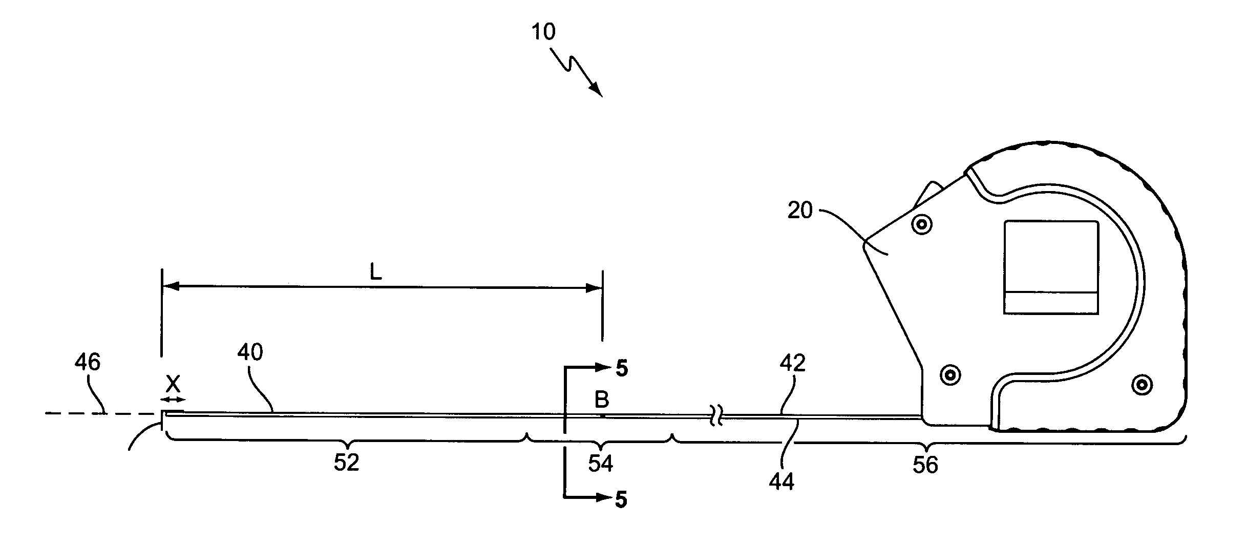
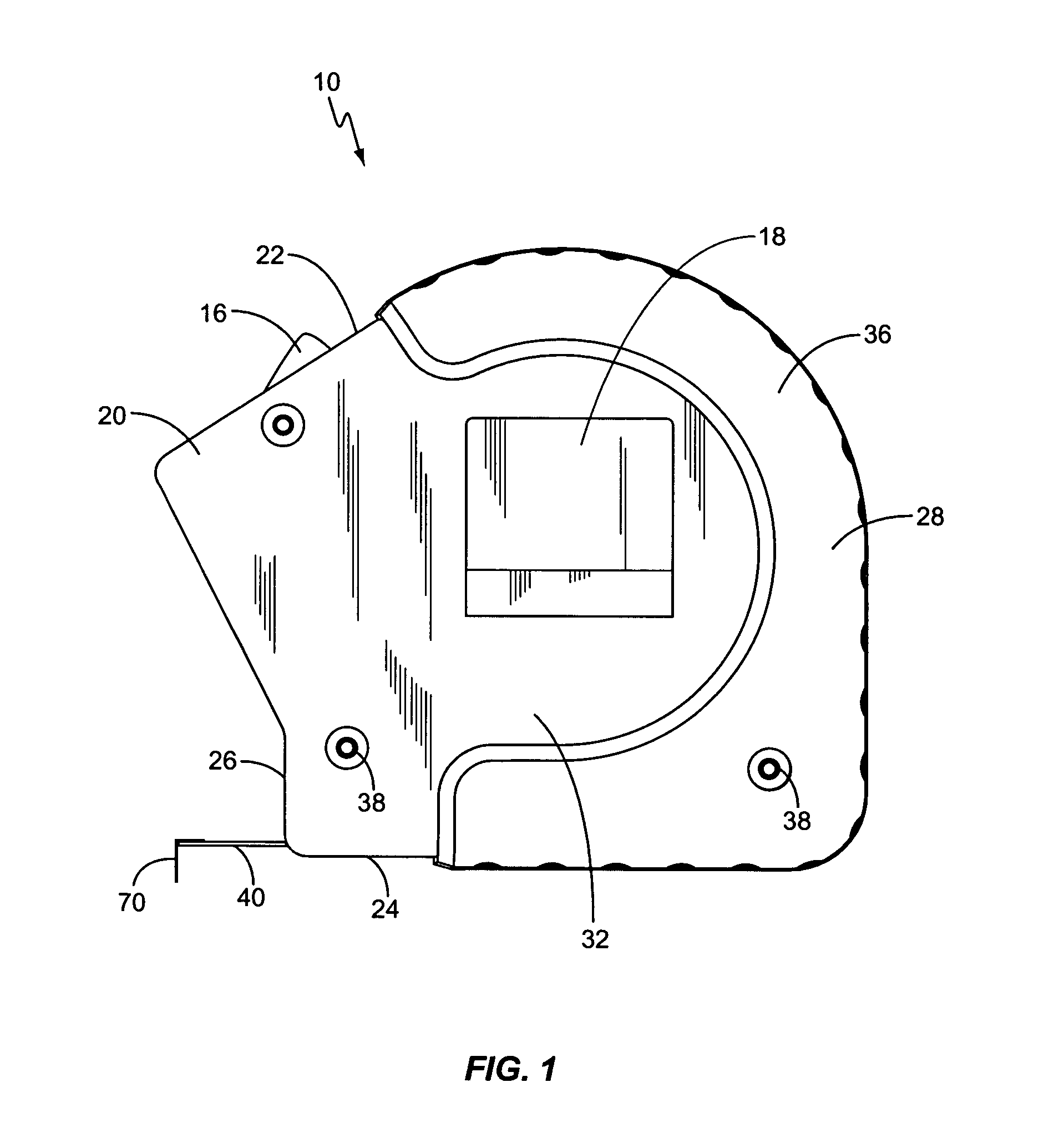
[0015]As illustrated in FIG. 1, a tape measure, generally designated 10, is shown constructed according to the present invention. The tape measure 10 includes a coilable measuring tape blade 40 and an associated housing 20. An end hook 70 is attached to the distal end of the tape 40. A tape-biasing device, such as a retraction spring (not shown), is operatively connected to the tape 40 to bias it towards a retracted orientation. A locking mechanism, including a toggle 16 or similar actuator is provided to aid in controlling the movement of the tape 40 into and out of the housing 20. One or both sides of the housing 20 may include a clip 18, as desired.

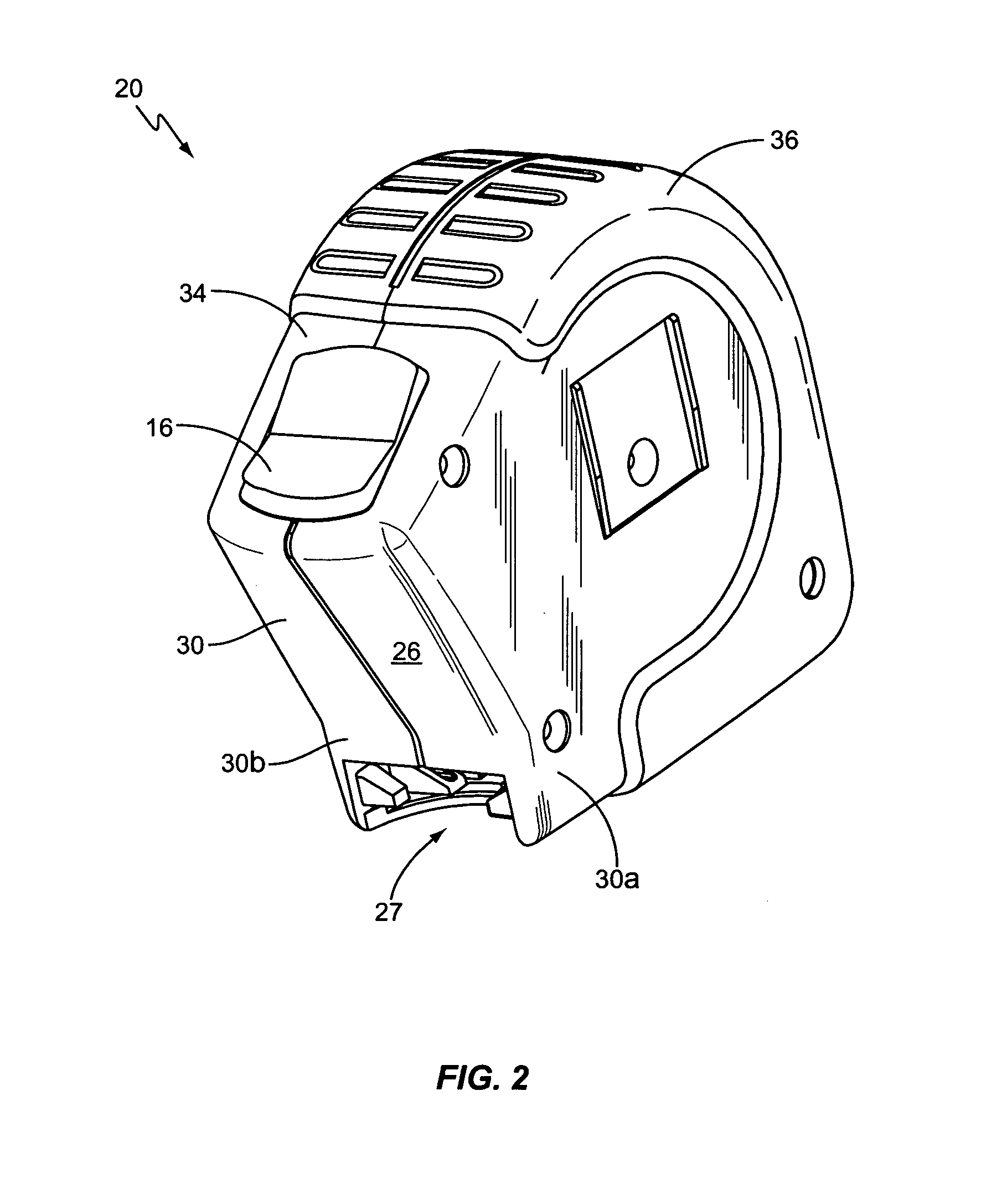
[0016]The housing 20 typically includes a main case or shell 30 and a grip element 36 mounted on the shell 30. The housing 20 preferably has a generally squarish shape, with a rounded upper-rear corner and may have a slightly projecting nose, as shown in FIGS. 1–2. The housing 20 includes an opposing pair of sidewalls 32 and an interco...


PUM


Abstract

A tape measure comprises a main case having first and second sidewalls and a peripheral wall extending between the sidewalls; a flexible tape blade selectively deployable from the case; the tape blade having a generally curved cross-sectional profile when deployed from the main case and having a generally flat profile when retracted into the main case; a hook attached to a first end of the tape blade so as to be movable a distance along a longitudinal axis of the tape blade; the hook having a first section disposed generally parallel to the longitudinal axis and a second section connected thereto and disposed generally normal to the longitudinal axis, the hook having a weight factor of not more than about 0.60. The tape blade may advantageously be not more than about 1.10 inch in width and have a standout of at least 9½ feet.

Description

[0001]This application claims the benefit of U.S. Provisional Application No. 60 / 533,093, filed 30 Dec. 2003.BACKGROUND OF THE INVENTION[0002]The present invention is directed generally to tape measures, and more particularly to power return tape measures.[0003]Modern tape measures (or “tape rules”) typically include a coiled tape that is spring-biased towards a retracted position. A housing generally surrounds and protects the tape and a retraction spring and includes an opening through which a distal end of the tape extends. Typically, the tape measure housing consists of two housing halves that are joined together by one or more screws. In addition, one of the housing halves typically includes an inwardly pointing integral post that provides an anchoring point for one end of the retraction spring. During assembly, the reel is placed over the post with the retraction spring engaged by the post, and the other housing half is then joined to the first housing half with blade winding ...

Claims


Application Information

Patent Timeline
Patent Type & Authority Patents(United States)
IPC IPC(8): G01B3/02G01B3/10
CPCG01B1/00G01B3/1056G01B3/1082G01B2003/1053G01B2003/1046G01B3/1046G01B3/1003G01B3/10
Inventor CRITELLI, JAMES M.BLACKMAN, WILLIAM C.GILLIAM, EDGAR T.DUHPORNE, DARIN H.OWEN, JOHN R.
Owner APEX BRANDS
Why Eureka
Try Eureka