Smart junction box for solar cell module

a solar cell module and smart technology, applied in the direction of electrical apparatus casings/cabinets/drawers, coupling device connections, hermetically sealed casings, etc., can solve the problems of difficult replacement during post-sale service, deterioration of the sealing efficiency of the shell, and damage to the contact parts of the bus bar or the body of the junction box, etc., to achieve convenient service, effective emitted, and stably operated

Inactive Publication Date: 2012-08-21
CONNEX ELECTRONICS +2
View PDF18 Cites 115 Cited by
  • Summary
  • Abstract
  • Description
  • Claims
  • Application Information

AI Technical Summary

Benefits of technology

[0018]As described above, the present invention has the effect of connecting or separating ribbon cables based on wide contact areas and high contact pressures by bringing the ribbon cable into contact with bus bars using pressing units.
[0019]Furthermore, the present invention enables the heat generated by ribbon cables and diodes to be effectively emitted to the outside by forming a heat sink structure in which bus bars, diodes and heat sink plates are fastened to each other in a surface contact relationship.
[0020]Furthermore, the present invention enables a junction box to be stably operated by using diodes which bypass current when an abnormality occurs in a cell of a solar cell module.
[0021]Furthermore, the present invention enables a junction box to be conveniently serviced because an operator can easily connect, or separate ribbon cables.
[0022]Furthermore, the present invention enables a rapid action to be taken by installing a smart module inside a junction box and rapidly providing a report to an administrator in real time when a solar ceil module fails or an abnormality occurs.

Problems solved by technology

Soldering deteriorates processing efficiency and makes replacement during post-sale service difficult, and the contact portions of bus bars or the body of a junction box may be damaged because ribbon cables are connected by exerting physical force using a driver so as to insert the ribbon cables into driver insertion recesses.
Furthermore, in the case where ribbon cables are folded and then connected, heat is generated due to high contact resistance and contact stability is also low because the ribbon cables are folded and then used, and additional post-processing is required to be performed on the ribbon cables because the ribbon cables should be folded and then connected.
As described above, since the conventional methods are problematic in that the body of a junction box may be damaged during the post-sale service of the junction box and post-processing is required to be performed on ribbon cables, a junction box having a structure which enables the easy connection of ribbon cables is required.
Furthermore, with regard to the conventional solar cell modules, since it is possible to track abnormalities occurring in each group of modules when the abnormalities occur, it is difficult to perform management and take action in real time because it is difficult to find the occurrence of an abnormality in each module, with the result that a solution to this is also required.

Method used


Image

  • Smart junction box for solar cell module
  • Smart junction box for solar cell module
  • Smart junction box for solar cell module

Examples


Embodiment Construction

[0036]The above-described objects, features and advantages will be more apparent from the following embodiments taken in conjunction with the accompanying drawings. The detailed embodiments of the present invention will be described in detail below with reference to the accompanying drawings.

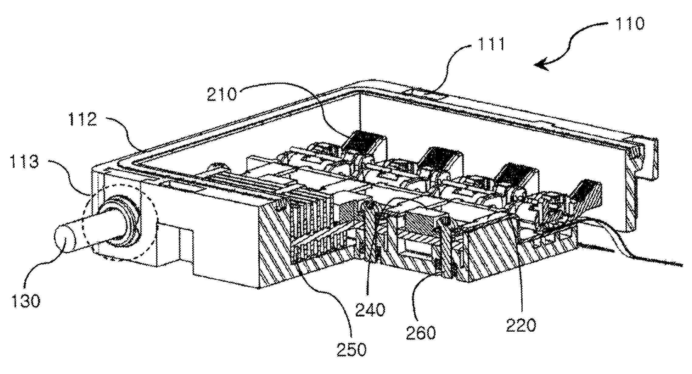
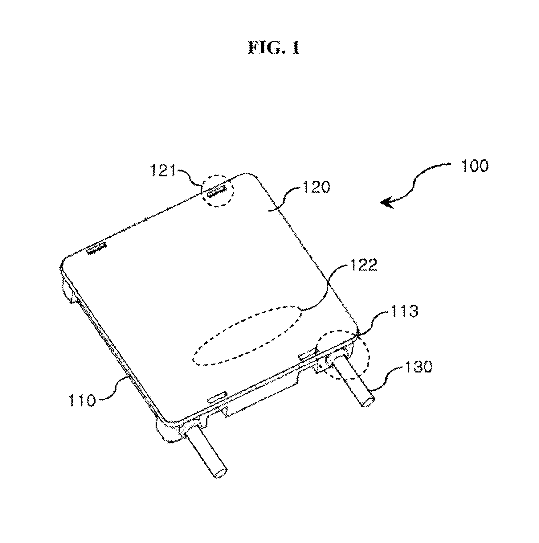
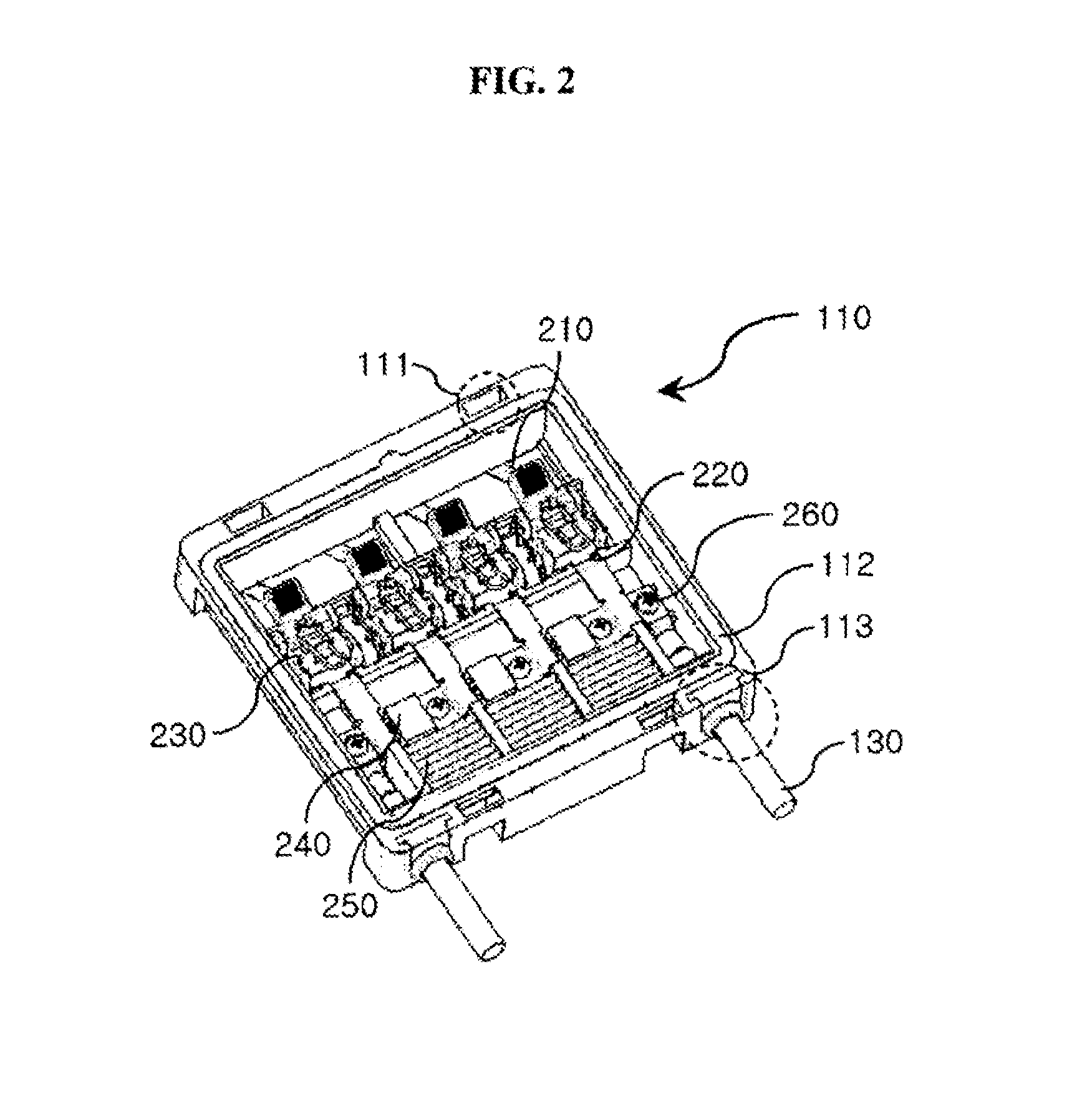
[0037]FIG. 1 is a perspective view showing a smart junction box for a solar ceil module according to an embodiment of the present invention, FIG. 2 is a perspective view showing the interior of the smart junction box for a solar cell module according to the embodiment of the present invention, and FIG. 3 is a perspective view showing the smart junction box for a solar cell module of FIG. 2 with part of the interior thereof cut away therefrom.

[0038]As shown in FIGS. 1 to 3, the junction box 100 for a solar cell module according to the embodiment of the present invention includes a body 110 attached to the back of the solar cell module and configured such that elements of the junction box are moun...


PUM


Abstract

The present invention relates to a smart junction box for a solar cell module, and provides a smart junction box for a solar cell module which enables an operator to easily connect and separate ribbon cables using the operation of the levers of pressing units, thereby being able to improve the contact stability of ribbon cables, and which has a heat sink structure, thereby effectively emitting the heat generated by the ribbon cables and the diodes to the outside. For this purpose, the smart junction box for a solar cell module of the present invention includes bus bars for transmitting electricity flowing from ribbon cables; and pressing units for selectively fastening and separating the ribbon cables located on contact portions of the bus bars depending on whether both ends of the lever projected by the manipulation of an operator are inserted into recesses formed in a body.

Description

TECHNICAL FIELD[0001]The present invention relates to a smart junction box for a solar cell module. In particular, the present invention relates to a smart junction box for a solar cell module which enables an operator to easily connect and separate ribbon cables using the operation of the levers of pressing units, thereby being able to improve the contact stability of ribbon cables. Furthermore, the present invention relates to a smart junction box for a solar cell module which has a heat sink structure in which ribbon cables, diodes, bus bars and heat sink plates are fastened to each other in a surface contact relationship, thereby effectively emitting the heat generated by the ribbon cables and the diodes. Moreover, the present invention relates to an intelligent junction box for a solar cell module in which sensors for detecting current, voltage and temperature are installed inside the junction box and sensed data is reported to an administrator using a smart module and a commun...

Claims


Application Information

Patent Timeline
Patent Type & Authority Patents(United States)
IPC IPC(8): H05K7/20H02G3/16
CPCH02S40/345H02S40/34Y02E10/50H02S50/00
Inventor HAN, YUN HEUIRHO, HEE CHANGKIM, HUN HOYOON, YONG SOO
Owner CONNEX ELECTRONICS
Why Eureka
Try Eureka