Ultrasonic diagnostic apparatus

a diagnostic apparatus and ultrasonic technology, applied in the field of ultrasonic diagnostic equipment, can solve the problems of difficult to accurately measure the geometric value such as the length, the area, or the volume of the region of interest, and the difficulty of obtaining the longitudinal image or the tomographic image of the subject accurately

Active Publication Date: 2005-04-28
OLYMPUS CORP
View PDF5 Cites 105 Cited by
  • Summary
  • Abstract
  • Description
  • Claims
  • Application Information

AI Technical Summary

Benefits of technology

[0009] It is an object of the present invention to at l

Problems solved by technology

As a result, the longitudinal image or the tomographic image of the subject displayed by the apparatus is often strained, as compared with an actual shape of the subject.
If the operator uses this apparatus, it is difficult to obtain the longitudinal image or the tomographic image of the subject which accurately represents the actual shape of the subject, and properly grasp the shape, size, or the like of the region of interest of the subject such as the characteristic site

Method used


Image

  • Ultrasonic diagnostic apparatus
  • Ultrasonic diagnostic apparatus
  • Ultrasonic diagnostic apparatus

Examples


first embodiment

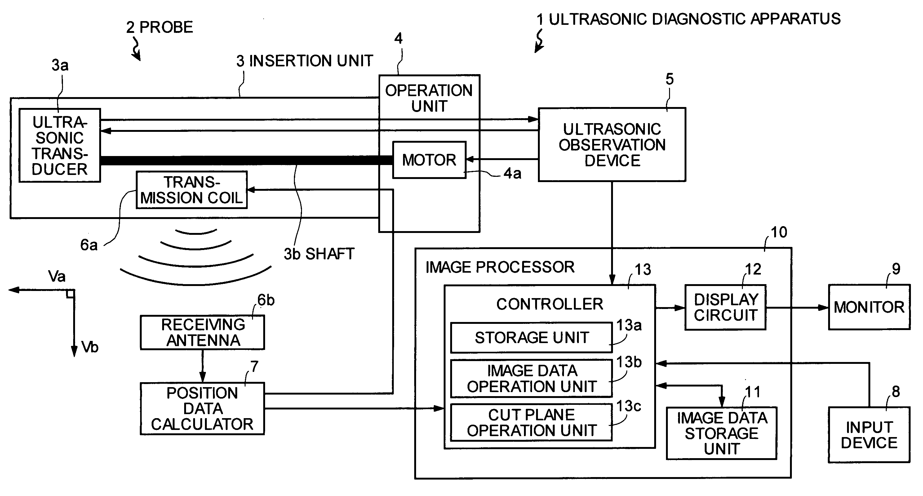
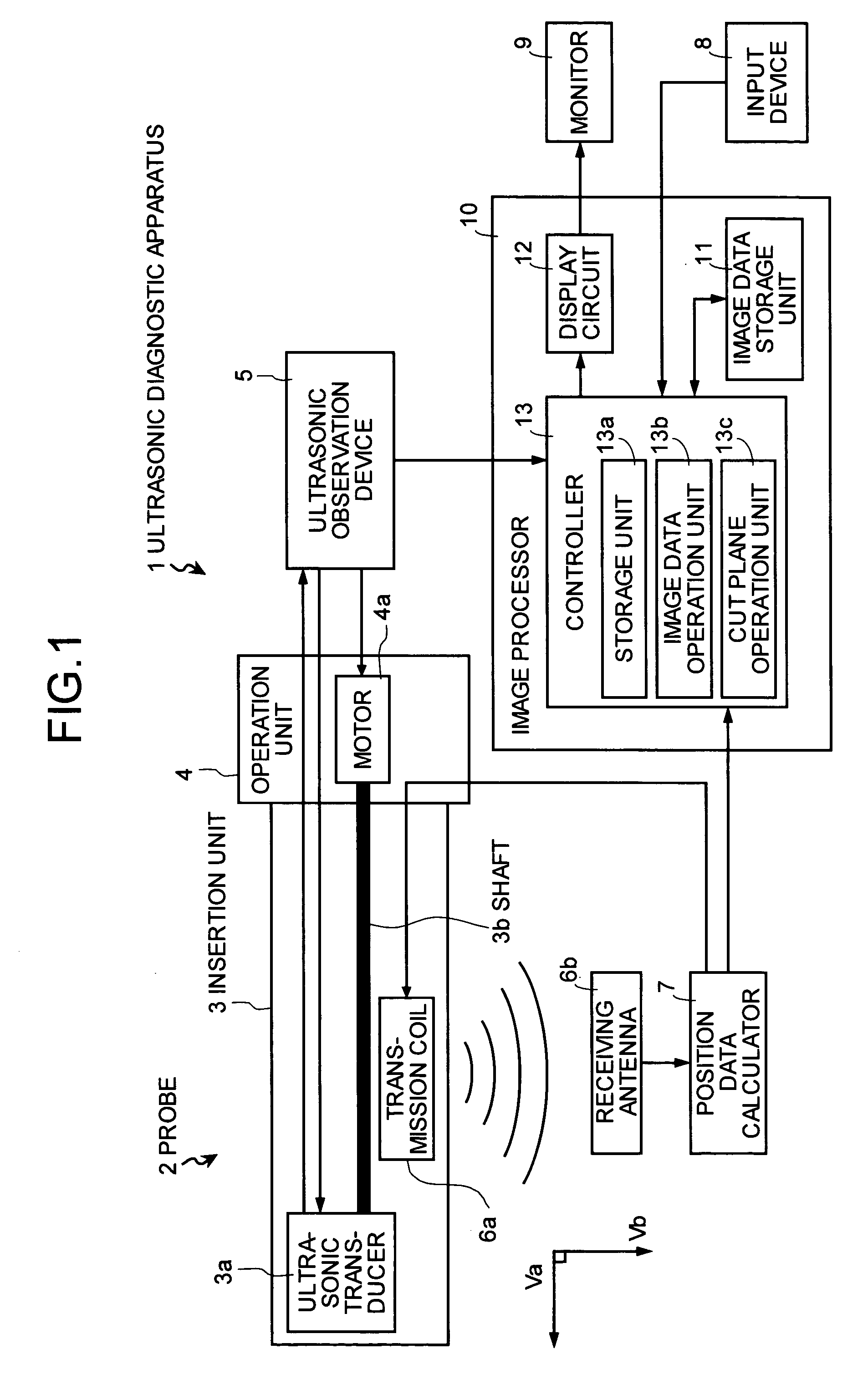
[0094]FIG. 1 is a block diagram that depicts schematic configuration of an ultrasonic diagnostic apparatus according to the present invention. In FIG. 1, the ultrasonic diagnostic apparatus 1 includes a probe 2 that includes an insertion unit 3 inserted into a living body and an operation unit 4 that operates the insertion unit 3, an ultrasonic observation device 5, a receiving antenna 6b, a position data calculator 7, an input device 8, a monitor 9, and an image processor 10. An ultrasonic transducer 3a is rotatably incorporated into a tip end of the insertion unit 3, and the operation unit 4 is arranged on a rear end of the insertion unit 3. A transmission coil 6a is detachably arranged near the ultrasonic transducer 3a. The operation unit 4 includes a motor 4a. The motor 4a is connected to the ultrasonic transducer 3a through a shaft 3b. The ultrasonic observation device 5 is electrically connected to the ultrasonic transducer 3a and the motor 4a through a power switch (not shown...

second embodiment

[0165] In the second embodiment, the instance in which one default point is updated to the new cut point is explained. However, the present invention is not limited to this instance. The two default points set on the 2D image data may be changed or the already set cut points may be changed to new cut points.

[0166] According to the second embodiment, the instance in which default point data on the default points are stored in the storage unit in advance is explained. However, the present invention is not limited to this instance. Before the 3D scan, the operator may operate the input device 8 to input the default points data.

[0167] According to the second embodiment, the pieces of 2D image data sequentially obtained by the 3D scan are cut at designated longitudinal plane positions, the adjacent pieces of one-column image data set at the longitudinal plane positions are linearly interpolated, and the longitudinal image generated by the linear interpolation is displayed on the monitor...

third embodiment

[0185] In the third embodiment, the adjacent pieces of 2D image data are linearly interpolated for the upper ends, lower ends, and side ends of the n pieces of 2D image data arranged on the spatial coordinate system xyz, and the upper plane image, the lower plane image, and the side plane image are thereby formed. However, the present invention is not limited to this instance. An image processing such as linear interpolation may be performed on all pixels between the respective adjacent pieces of 2D image data, thereby forming the upper plane image, the lower plane image, and the side plane image.

[0186] According to the third embodiment, the 2D ultrasonic tomographic image obtained first by the 3D scan and the 2D ultrasonic tomographic image obtained last by the 3D scan are connected to the front end and the rear end of the 3D longitudinal image of the cut surfaces set based on the cut suface information, i.e., the band-shaped 3D longitudinal image, respectively, thereby generating ...


PUM


Abstract

An ultrasonic diagnostic apparatus including: an ultrasonic observation device that transmits and receives an ultrasonic wave by an ultrasonic transducer arranged on a tip end of a probe, and that acquires a plurality of two-dimensional ultrasonic tomographic images for a subject in a living body; a position data calculator that detects information indicating a reference position of each of the two-dimensional ultrasonic tomographic images and an orientation of a tomographic plane of the each two-dimensional ultrasonic tomographic image; and an image processor is provided. The image processor generates a band-shaped longitudinal image including a curved plane along a moving path of the ultrasonic transducer.

Description

CROSS-REFERENCE TO RELATED APPLICATIONS [0001] This application claims the benefit of priority of Japanese Patent Applications No. 2003-354316 filed on Oct. 14, 2003 and No. 2003-401434 filed on Dec. 1, 2003, the entire contents of which are incorporated herein by reference. BACKGROUND OF THE INVENTION [0002] 1) Field of the Invention [0003] The present invention relates to an ultrasonic diagnostic apparatus which irradiates a subject, such as a living body, with an ultrasonic wave, receives an echo of the ultrasonic wave, performs three-dimensional (hereinafter, “3D”) scan, and which displays a desired tomographic image of the subject on a monitor screen using 3D region image data obtained by the 3D scan. [0004] 2) Description of the Related Art [0005] Conventionally, an ultrasonic diagnostic apparatus which irradiates a subject, such as a living body, with an ultrasonic wave, spatially receives an echo of the ultrasonic wave, performs 3D scan on the subject, generates 3D image dat...

Claims


Application Information

Patent Timeline
IPC IPC(8): A61B5/06A61B5/107A61B8/12A61B8/14
CPCA61B5/06A61B5/1076A61B8/12A61B8/483A61B8/4254A61B8/463A61B8/14
Inventor KAWASHIMA, TOMONAOYOKOI, SHUN
Owner OLYMPUS CORP
Why Eureka
Try Eureka