Methods and apparatus for antenna control in a wireless terminal

a wireless terminal and antenna control technology, applied in the field of methods and apparatus for improving communication, can solve the problems of increasing cost, size, weight, power consumption, and slow testing between different potential test coefficient sets for each channel quality measurement, and achieves improved communication channels, improved wireless terminal antenna coefficient combination, and low cost

Active Publication Date: 2006-09-14
QUALCOMM INC
View PDF25 Cites 98 Cited by
  • Summary
  • Abstract
  • Description
  • Claims
  • Application Information

AI Technical Summary

Benefits of technology

[0017] In accordance with the present invention, the base station need not, and in many cases does not, know switching information and/or the sets of antenna coefficients being used by the wireless terminals. However, the base station benefits from the improved communication channels obtained by the wireless terminal switching selection which uses th...

Problems solved by technology

This approach has the disadvantages that two filters and two RF receiver chains are required, which increases cost, size, weight, and po...

Method used


Image

  • Methods and apparatus for antenna control in a wireless terminal
  • Methods and apparatus for antenna control in a wireless terminal
  • Methods and apparatus for antenna control in a wireless terminal

Examples


Embodiment Construction

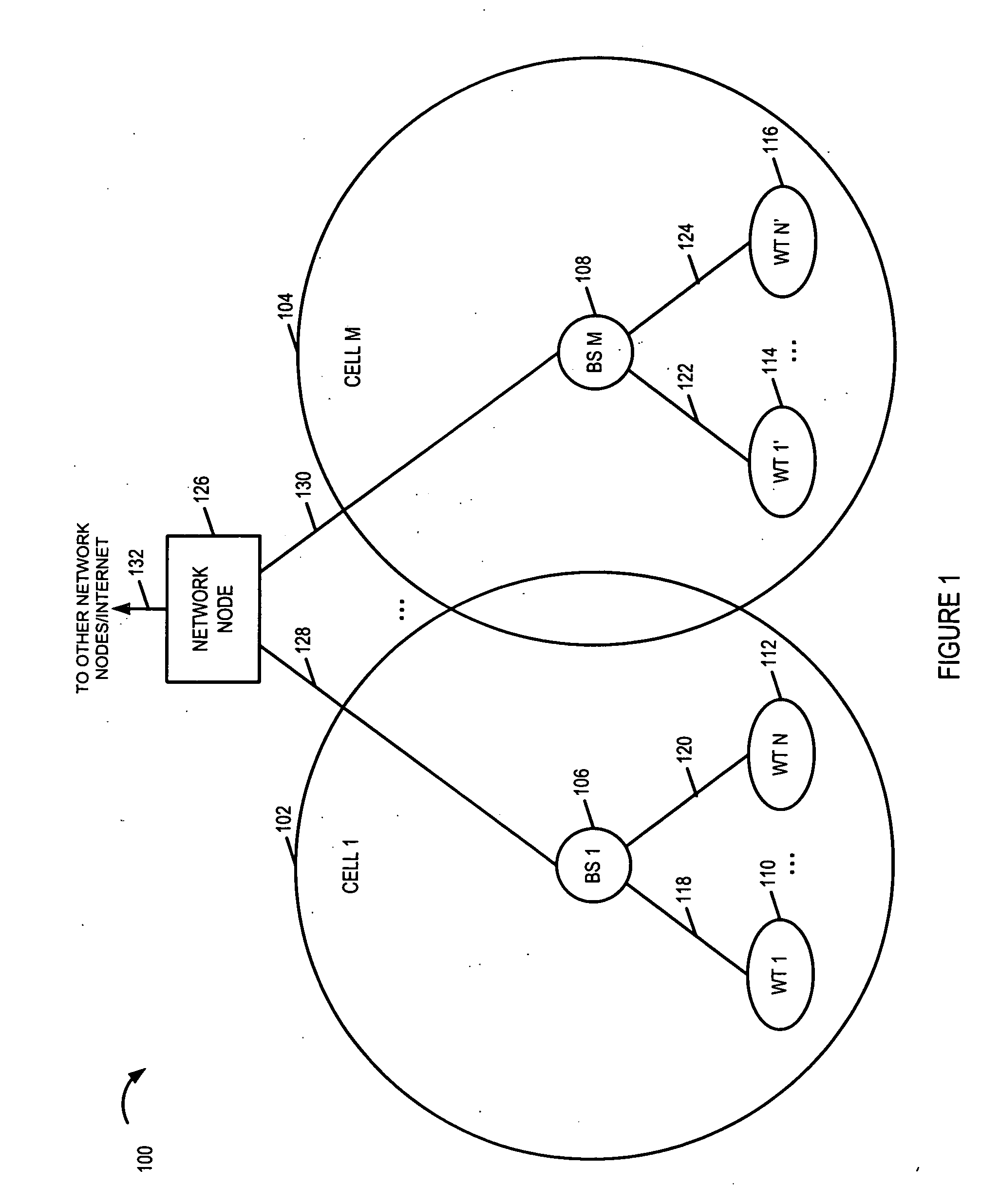
[0041]FIG. 1 is a drawing of an exemplary communications system 100, implemented in accordance with the present invention and using methods of the present invention. Exemplary system 100 may be, e.g., an orthogonal frequency division multiplexing (OFDM) multiple access wireless communication system. System 100 includes a plurality of cells (cell 1102, cell M 104). Each cell (cell 1102, cell M 104) represents a wireless coverage area for a corresponding base station (BS 1106, BS M 108), respectively. A plurality of wireless terminal (WTs) (WT 1110, WT N 112, WT 1′114, WT N′116) are included in system 100. At least some of the WTs are mobile nodes (MNs); the MNs may move throughout the system 100 and establish wireless links with different BSs, the BS corresponding to the cell in which the WT is currently located. In FIG. 1, (WT 1110, WT N 112) are coupled to BS 1106 via wireless links (118, 120), respectively; (WT 1′114, WT N′116) are coupled to BS M 108 via wireless links (122, 124)...


PUM


Abstract

Base stations transmit strip signals using strip signal segments and self supporting modulation scheme techniques facilitating rapid channel estimate. A strip segment occupies one OFDM symbol time interval and uses a set of downlink tones; some, e.g., half, of the tones are left unused facilitating SIR measurement. The strip segments are advantageously timed to correspond to uplink access intervals in which connected wireless terminals do not typically transmit uplink signals. Connected wireless terminals including: multiple antennas used in combination, an antenna duplex module, single RF receiver chain and single RF transmitter chain, switch antenna coefficient combinations based on strip signal segment timing. The wireless terminal determines an independent downlink channel quality measurement, e.g., SNR and/or SIR for each strip signal segment and for on-going non-strip signaling. The wireless terminal compares channel quality measurements and selects an antenna coefficient combination to be used during non-strip signaling intervals obtaining very good antenna gain.

Description

RELATED APPLICATIONS [0001] The present application claims the benefit of U.S. Provisional Patent Application Ser. No. 60 / 660,022, filed on Mar. 9, 2005, titled “METHODS AND APPARATUS FOR STRIP BASED SWITCHABLE ANTENNA”, which is hereby expressly incorporated by reference.FIELD OF THE INVENTION [0002] The present invention relates to methods and apparatus for improving the communications for wireless communication devices including multiple antennas. BACKGROUND OF THE INVENTION [0003] One approach to measuring and evaluating different antenna coefficient combinations with multiple receive antennas is to route the outputs of the multiple receive antennas to different combining filters. One filter can be set to the set of antenna coefficients being used for current downlink signal processing, and that filter's output can be routed to the input of a 1st RF processing chain in the receiver. A second filter can be set to a second set of antenna coefficients, e.g., a set of test coefficie...

Claims


Application Information

Patent Timeline
IPC IPC(8): H04B7/00
CPCH04B7/0811H04B7/0848H04B7/088
Inventor LAROIA, RAJIVLI, JUNYILANE, FRANK A.
Owner QUALCOMM INC
Why Eureka
Try Eureka