Battery pack-cordless power device interface system

a power device and battery pack technology, applied in the direction of coupling device connection, secondary cell servicing/maintenance, instruments, etc., can solve the problems of not being able to achieve the advantages provided, not being able to use integral batteries, and cordless power devices such as cordless power tools are not well suited to use integral batteries

Inactive Publication Date: 2007-01-09
BLACK & DECKER INC
View PDF8 Cites 87 Cited by
  • Summary
  • Abstract
  • Description
  • Claims
  • Application Information

AI Technical Summary

Problems solved by technology

Plugging such a cordless power tool into a charger during use would be inconvenient, obviating the advantages provided by a cordless power tool, and in some cases isn't possible due to the lack of AC mains power where the cordless power tool is being used.
For these reasons, cordless power devices such as cordless power tools are not well suited for using integral batteries.
They include the possibility of thermal imbalance due to the “tower-cell” being separated from the larger cluster of cells in the main body of the battery pack and thus tends to be at a different temperature during operation of the tool.
The “tower-cell” design also typically introduces extra manufacturing processes and components, thus increasing manufacturing complexity.
In a number of products utilizing the “tower-cell” interface system the “tower-cell” connections in the battery pack have presented reliability concerns.
Also, the entire weight of the battery pack is supported by the latches which secure the battery pack to the tool and the contact area of the latches to the tool tends to be small, placing a relatively high amount of stress on the latches.
They include rail contamination which makes insertion and removal of the battery pack more difficult.
Insertion and removal of the battery pack is awkward compared to the “tower-cell” design interface system in that two hands are typically required to insert or remove the battery pack.
Also, pushing or pulling on the battery pack during insertion and removal creates a moment about the tool making it more difficult to hold the tool in place.
The battery pack housing has a “clamshell” construction and the tolerances of the rail dimensions are difficult to hold in the assembly of the clamshell, making rail travel “sticky.” The foot of the tool has dead space in that there is no “tower-cell” that fills the space in the foot of the tool.

Method used


Image

  • Battery pack-cordless power device interface system
  • Battery pack-cordless power device interface system
  • Battery pack-cordless power device interface system

Examples


Embodiment Construction

[0045]The following description of the preferred embodiment(s) is merely exemplary in nature and is in no way intended to limit the invention, its application, or uses. For convenience, the invention will be discussed in the context of cordless power tools but it should be understood that it can be used in any cordless power device where battery packs are used.

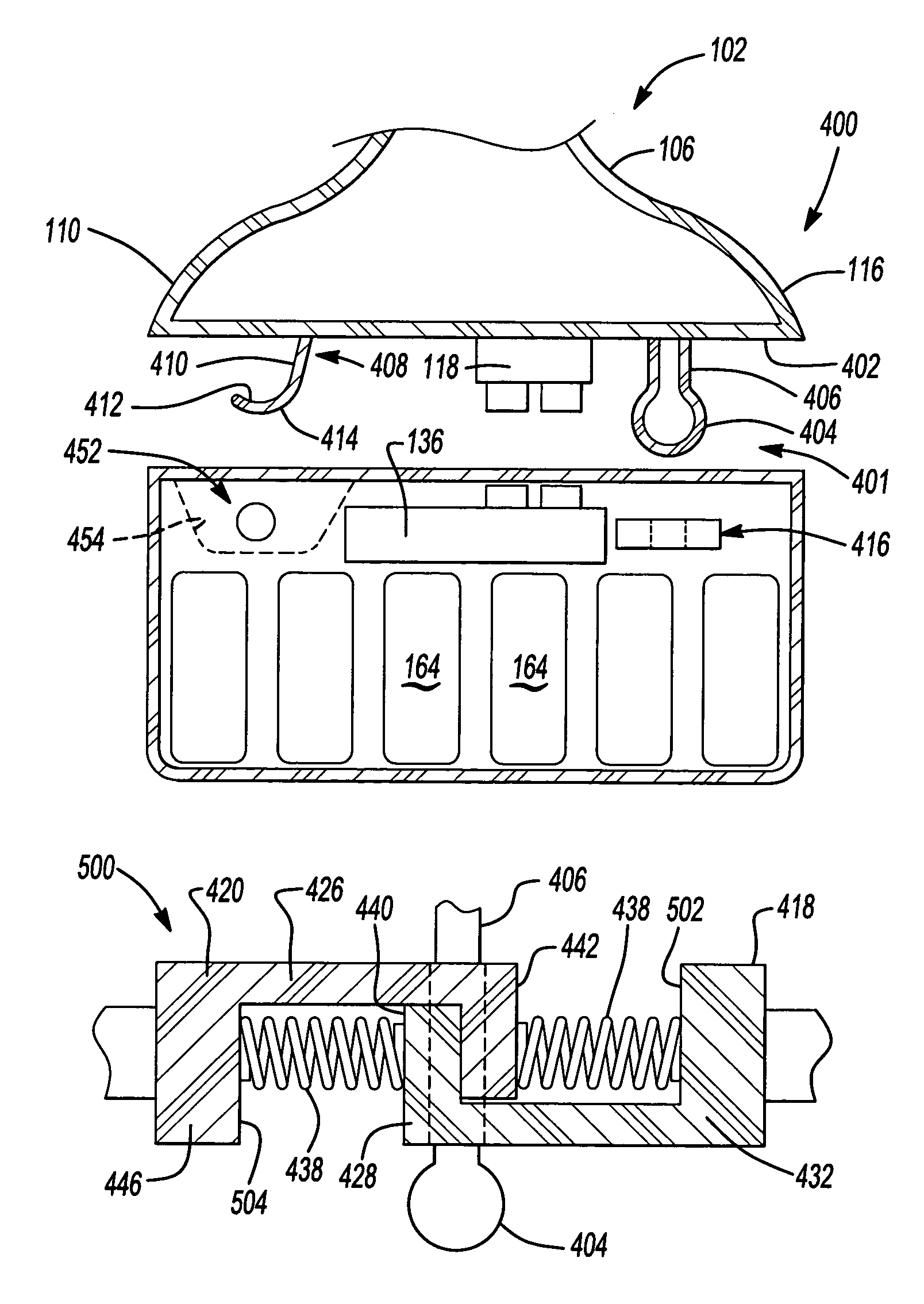
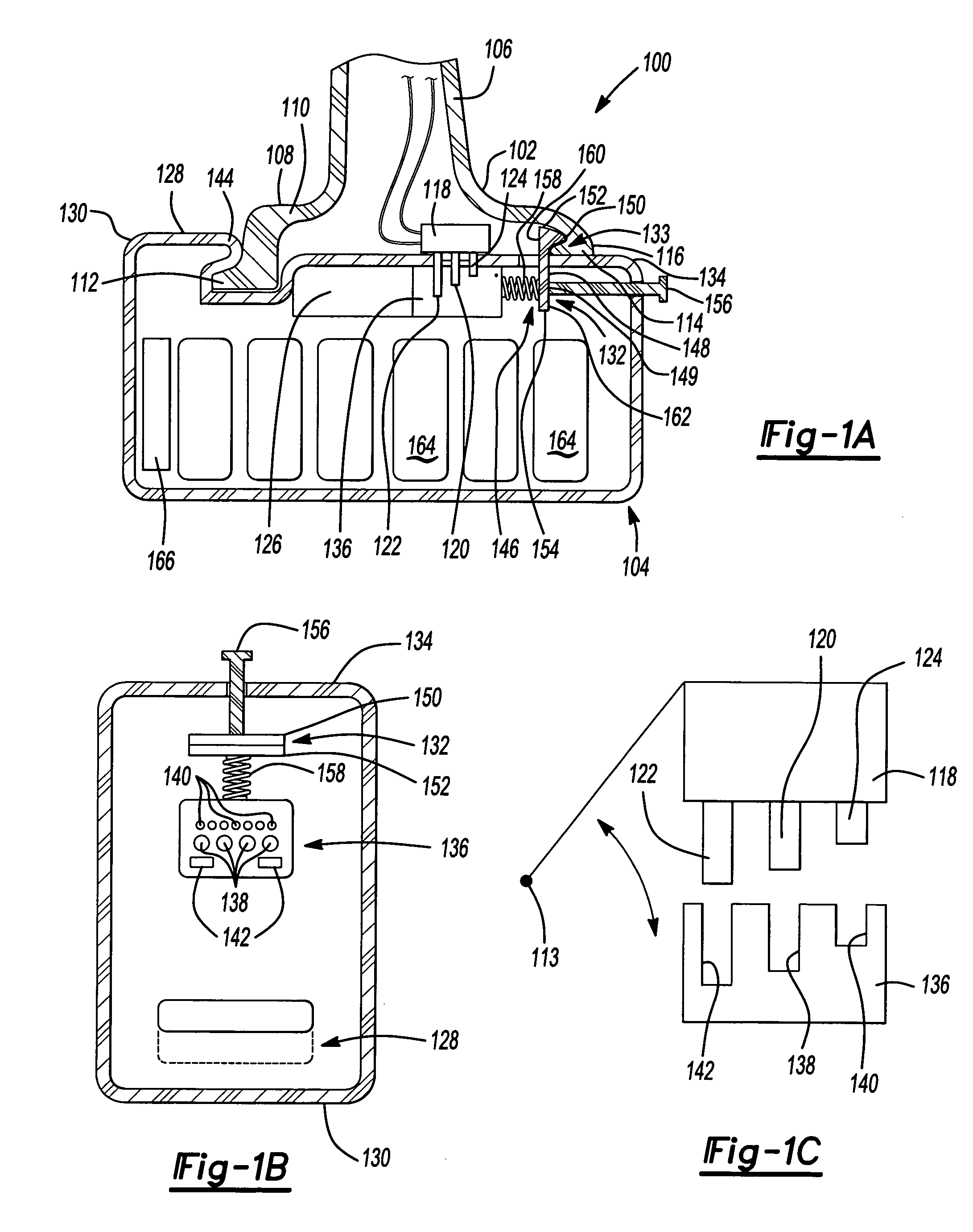
[0046]FIGS. 1A and 1B show an interface system 100 in accordance with an embodiment of the invention in a cordless power tool 102 and a removable battery pack 104. As used herein, “interface system” means the elements of the cordless power tool and the battery pack that are used in mating the cordless power tool and battery pack and securing the battery pack in the cordless power tool.

[0047]Interface system 100 includes a rear retention member 112 (illustratively an outwardly extending lip or flange) at a rear end 110 of a foot 108 of a housing 106 of cordless power tool 102. Interface system 100 also includes a front retentio...


PUM

PropertyMeasurementUnit
timeaaaaaaaaaa
rated voltageaaaaaaaaaa

Abstract

A battery pack for a cordless power tool and a cordless power tool and battery pack combination includes the battery pack having a retention member that pivotally engages a retention member of the power tool and a latch system in which one of the battery pack and power tool has a ball and the other of the power tool and battery pack has a latch that engages the ball. Spring biased actuators may be used to open the latch to enable insertion or release of the ball from the latch.

Description

CROSS-REFERENCE TO RELATED APPLICATIONS[0001]This application claims the benefit of U.S. Provisional Application No. 60 / 558,176 filed Mar. 31, 2004. The disclosure of the above application is incorporated herein by reference.FIELD OF THE INVENTION[0002]The present invention relates to cordless power devices that use battery packs, and more particularly, an interface system in a cordless power device and battery pack that interfaces the two together.BACKGROUND OF THE INVENTION[0003]Some cordless power devices have an integrated battery pack that rarely needs to be removed by the user. The battery pack remains in the device for both charge and discharge cycles. Cell phones are a typical example and have battery packs that are charged while installed in the phones. This is possible for two main reasons: the battery can usually provide sufficient power for the cell phone for a relatively long period of time such as one to two days, and the user is not severely inconvenienced by charging...

Claims


Application Information

Patent Timeline
Patent Type & Authority Patents(United States)
IPC IPC(8): H01R4/50B25F5/02G01R1/20H01M10/42H01M50/209H01M50/244H01M50/247H01M50/262H01M50/296H01R11/28H01R13/635H01R33/975H02J7/00
CPCB25F5/02H01M2/1022H01M2/1027H01M2/1033H01M2/1066H01R33/975H01M2/1055G01R31/3696Y10S439/953H01M10/42H01R11/282H01R13/635G01R31/364Y02E60/10H01M50/267H01M50/209H01M50/213H01M50/247H01M50/296H01M50/262H01M50/244
Inventor PHILLIPS, STEVEN J.BROTTO, DANIELE C.CARRIER, DAVID A.FRANCIS, JEFFREY J.SEMAN, JR., ANDREW E.TRINH, DANH THANHYAHNKER, CHRISTOPHER R.WATSON, JAMES B.WHITE, DANIEL J.
Owner BLACK & DECKER INC
Why Eureka
Try Eureka