
Linkage mechanism providing a virtual pivot axis for hair removal apparatus with pivotal head

Inactive Publication Date: 2007-01-16
THE GILLETTE CO
View PDF14 Cites 27 Cited by
  • Summary
  • Abstract
  • Description
  • Claims
  • Application Information

AI Technical Summary

Benefits of technology

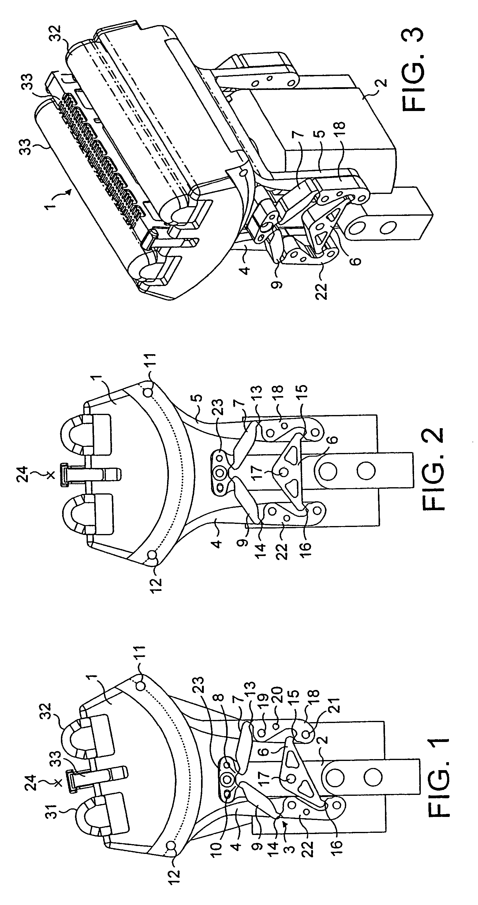
[0012]Ergonomic design freedom is maximized when said respective first ends of the second and third transverse link members are pivotally mounted on the body at eighth and ninth pivot axes which are spaced apart, and parallel to said first and second axes (see e.g. FIG. 14). Vertical compactness is optimized when a plane perpendicular to said parallel axes intersects said third, eighth and ninth axes at spaced points forming an isosceles triangle. It is also possible for said eighth and ninth axes to be colinear, which may simplify construction by reducing the number of components. In a symmetrical arrangement, said third, eighth and ninth axes and said virtual axis all lie in a common plane.
[0017]Alternatively, another compact arrangement is achieved when the distance between said first and sixth axes is greater than the distance between said first and fourth axes (see e.g. FIG. 17, FIG. 20). Although this will generally increase the vertical height of the mechanism, it may minimize the lateral width.

Problems solved by technology

Applicant herein has recognized that this is a disadvantage if it is desired to make the linkage mechanism more compact, for example to produce a slim housing.

Method used


Image

  • Linkage mechanism providing a virtual pivot axis for hair removal apparatus with pivotal head
  • Linkage mechanism providing a virtual pivot axis for hair removal apparatus with pivotal head
  • Linkage mechanism providing a virtual pivot axis for hair removal apparatus with pivotal head

Examples


Embodiment Construction

[0053]Several embodiments of the present invention will be described in the following.

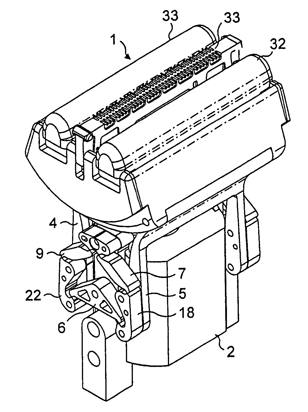
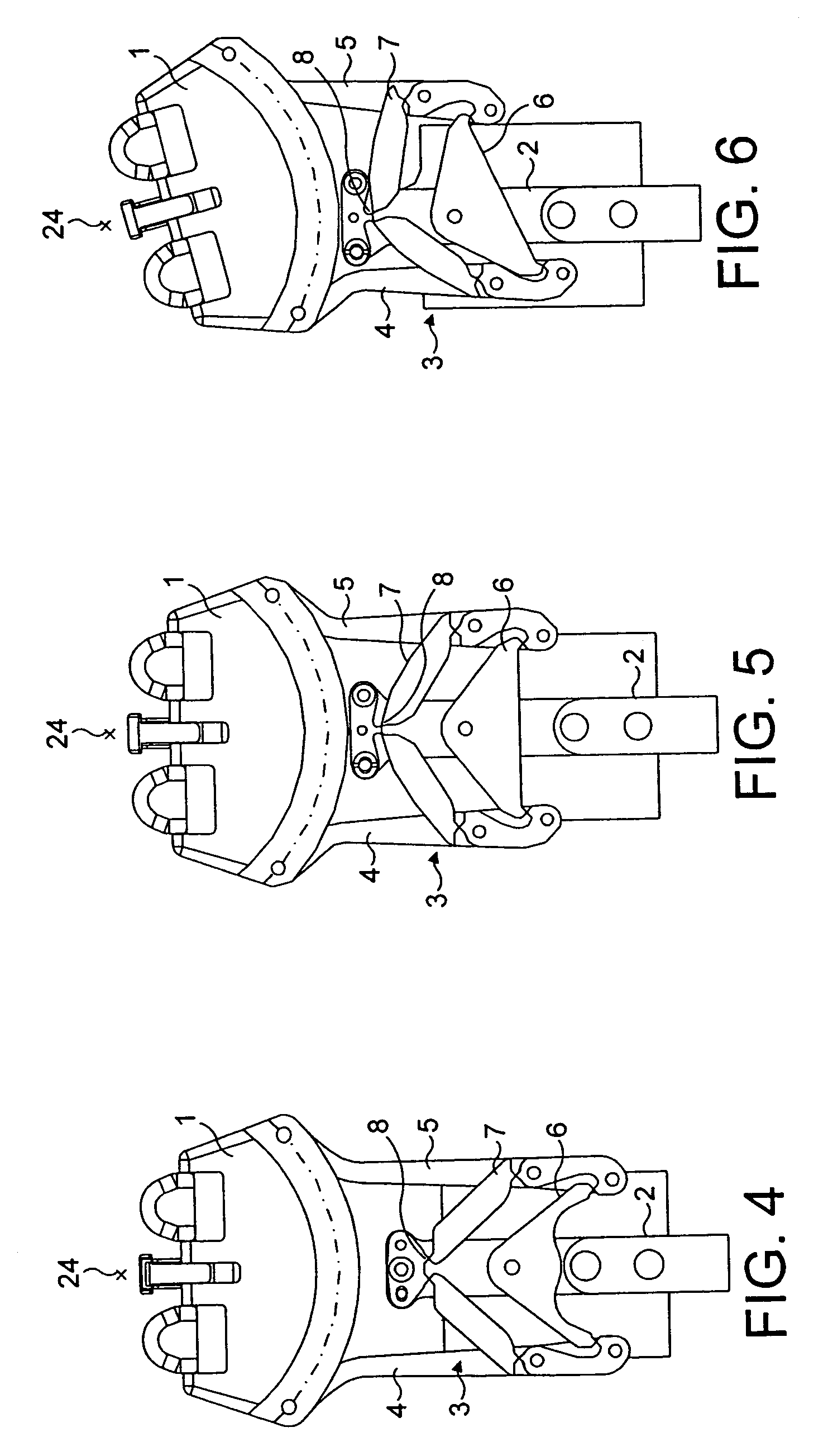
[0054]In the present invention, the constraint, for example, that the linkage be nearly as wide as its attachment location to the shaver head, is no longer necessary. The present invention employs an upper transverse linkage arrangement which is not congruent with the lower transverse linkage portion but which nevertheless generates a virtual pivot axis to permit rocking movement of the head of a dry shaver. The embodiments of the invention employ a five bar linkage comprising a main transverse link, two lateral support arms and two transverse stabilizing links. This permits a wide range of possible positions of the virtual pivot axis and also gives the designer the ergonomic freedom to package a large head with multiple shaving units together with a relatively thin and skinny handle.

[0055]In the conventional parallelogram linkage, the centres of rotation of the transverse links lie in a plane whic...


PUM


Abstract

A linkage mechanism for a shaver or depilator has a head carrying at least one hair removal member mounted for rocking about a virtual axis that remains nearly static during pivoting. The linkage mechanism five links, which include a pair of spaced support arms pivoting on the head. A first transverse link member rotates about a third axis and pivots on each of the support arms. Second and third transverse link members pivot on the body and on respective ones of the support arms.

Description

CROSS-REFERENCE TO RELATED APPLICATIONS[0001]This application claims priority under 35 U.S.C. § 119(a) from European Patent Application No. 02 022 221.2, filed on Oct. 1, 2002.FIELD OF THE INVENTION[0002]The present invention relates to a linkage mechanism for a hair removal appliance, such as a powered or “dry” shaver or epilator, having a head rockably mounted on a body, and to such hair depilation apparatus. The term “hair removal appliance” may herein alternatively be referred to by the generic designation “depilation appliance” understood to include such species of hair-removing appliances as shavers and epilators. The invention also relates to a method of mounting a component, e.g. a head, for rocking about a virtual pivot axis.BACKGROUND[0003]A dry shaver having a rockable head is known. The rocking of the shaver head facilitates good contact between the shaver head and the user's skin during shaving.[0004]WO 93 / 12916 (U.S. Pat. No. 6,098,289 (Wetzel et al.)) discloses a shav...

Claims


Application Information

Patent Timeline
IPC IPC(8): B26B19/04B26B21/52B26B19/10B26B21/22
CPCB26B19/048B26B21/225B26B19/10
Inventor ROYLE, TERENCE
Owner THE GILLETTE CO
Learn More