Rear drag operation structure for a spinning reel

a technology of rotating reels and operation structures, which is applied in the direction of reels, applications, fishing, etc., can solve the problems of difficult entry of foreign objects inside the reel unit, and achieve the effect of improving the design of the rear drag operation structur

Inactive Publication Date: 2007-01-23
SHIMANO INC
View PDF9 Cites 6 Cited by
  • Summary
  • Abstract
  • Description
  • Claims
  • Application Information

AI Technical Summary

Benefits of technology

[0008]In a rear drag operation structure for a spinning reel, it is an object of the present invention to make it difficult for foreign matter to enter inside the reel unit, and to improve the design of the rear drag operation structure.

Problems solved by technology

Thus, it is difficult for foreign matter to enter inside the reel unit.

Method used


Image

  • Rear drag operation structure for a spinning reel
  • Rear drag operation structure for a spinning reel
  • Rear drag operation structure for a spinning reel

Examples


Embodiment Construction

[0035]Selected embodiments of the present invention will now be explained with reference to the drawings. It will be apparent to those skilled in the art from this disclosure that the following descriptions of the embodiments of the present invention are provided for illustration only and not for the purpose of limiting the invention as defined by the appended claims and their equivalents.

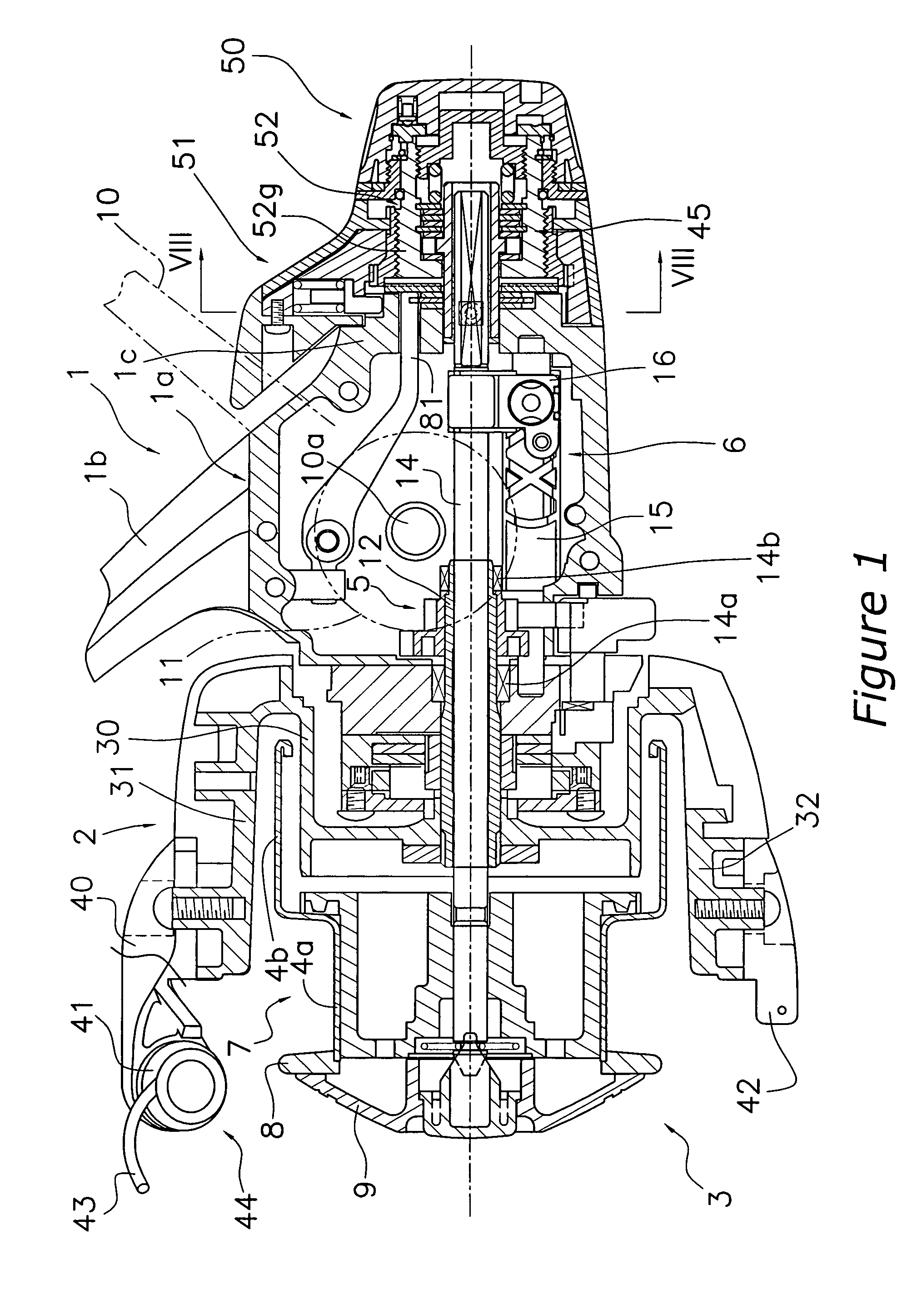
[0036]FIG. 1 shows a spinning reel according to an embodiment of the present invention.

[0037]As shown in FIG. 1, the spinning reel primarily includes a reel unit 1 that rotatively supports a handle 10, a rotor 2, a spool 3, a first rear drag knob 50, and a second rear drag knob 51.

[0038]Reel Unit

[0039]The reel unit 1 includes a reel body la, and a rod attachment leg 1b that extends diagonally upward and forward from the reel body 1a. An accommodation space is formed in the interior of the reel body 1a. A rotor drive mechanism 5 that rotates the rotor 2 in conjunction with the rotation of the handle...


PUM


Abstract

The rear drag operation structure includes a knob mounting portion, a first rear drag knob, and a second rear drag knob. The knob mounting portion includes a tubular portion that projects rearward from the rear portion of the reel unit, and a male threaded portion formed on the outer peripheral surface of the tubular portion. The first rear drag knob is mounted on the rear end portion of the knob mounting portion. The second rear drag knob includes lever members that are disposed between the rear portion of the reel unit and the front portion of the first rear drag knob, and a nut member that is mounted on the lever members so as to be not rotatable but moveable forward and backward relative thereto, and is screwed onto the male threaded portion of the knob mounting portion.

Description

BACKGROUND OF THE INVENTION[0001]1. Field of the Invention[0002]The present invention generally relates to a rear drag operation structure. More specifically, the present invention relates to a rear drag operation structure that serves to operate a rear drag mechanism that is arranged on the rear of a reel unit of a spinning reel.[0003]2. Background Information[0004]With conventional spinning reels, a rear drag operation structure that serves to operate a rear drag mechanism arranged on the rear of a reel unit has been widely adopted.[0005]A conventional rear drag operation structure includes a knob mounting portion, a first rear drag knob, and a second rear drag knob (see, for example, Japanese Utility Model Publication 3-5259. FIG. 1). The knob mounting portion includes a tubular portion and a male threaded portion. The tubular portion has a tubular shape that projects rearward from the rear portion of the reel unit, and the male threaded portion is formed on an outer peripheral s...

Claims


Application Information

Patent Timeline
Patent Type & Authority Patents(United States)
IPC IPC(8): A01K89/02A01K89/01A01K89/027
CPCA01K89/027A01K89/029A01K89/0114A01K89/01
Inventor KITAJIMA, KEIGO
Owner SHIMANO INC
Why Eureka
Try Eureka