
Multiple-position push-on electrical connector

a technology of push-on and electrical connectors, which is applied in the direction of two-pole connection, coupling device connection, printed circuit, etc., can solve the disadvantage of large disadvantages of multiple-position coaxial cable connectors, the plurality cannot be uncoupled from the plurality, and the process of soldering a coaxial cable to the cable adapter is slow

Active Publication Date: 2007-01-23
CORNING OPTICAL COMM LLC
View PDF28 Cites 96 Cited by
  • Summary
  • Abstract
  • Description
  • Claims
  • Application Information

AI Technical Summary

Benefits of technology

"The present invention provides a multi-position connector with smaller dimensions than prior art connectors. It also allows for field replacement of individual coaxial cables attached to the connector and allows for multiple coaxial cable-to-PWB connections to be made and broken with a single action."

Problems solved by technology

Disadvantageously, the plurality of coaxial cables cannot be uncoupled from the plurality of single-position connectors with a single action.
Furthermore, known single-position microwave connectors having a push-on style interface have a cable adapter that is press-fit into the connector body, thereby disadvantageously being thermally integral with the connector body, which can slow the process of soldering a coaxial cable to the cable adapter.
Such known multiple-position coaxial cables connectors are disadvantageously relatively large—usually about two inches in diameter.
However, all known multiple-position connectors designed to connect a coaxial cable to a PWB lack any provision to allow the coaxial cables to be individually field replaceable.

Method used


Image

  • Multiple-position push-on electrical connector
  • Multiple-position push-on electrical connector
  • Multiple-position push-on electrical connector

Examples


Embodiment Construction

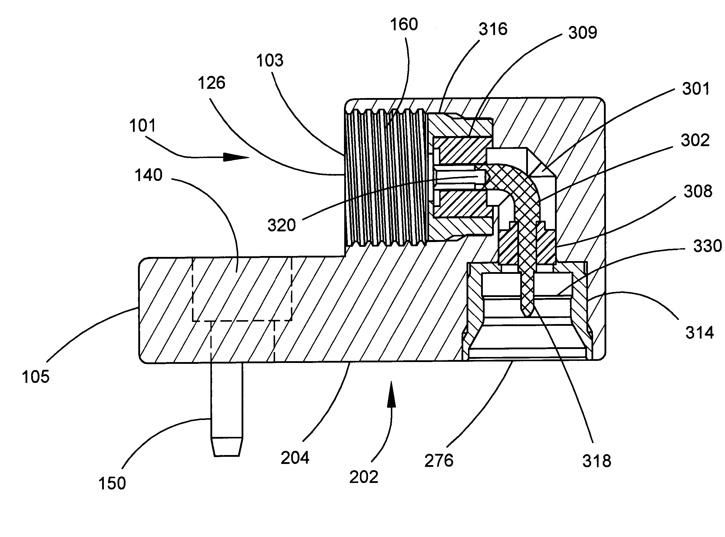
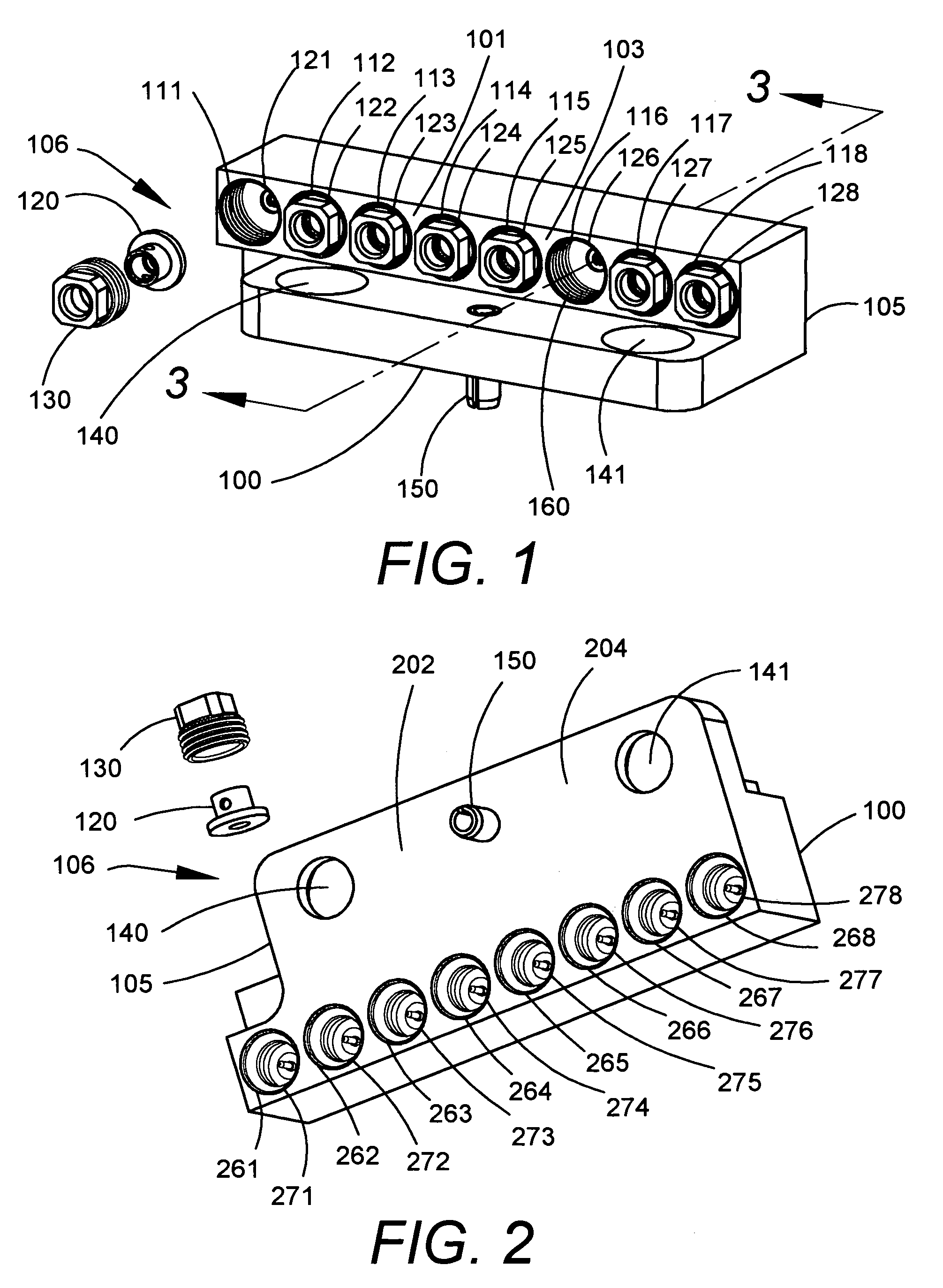
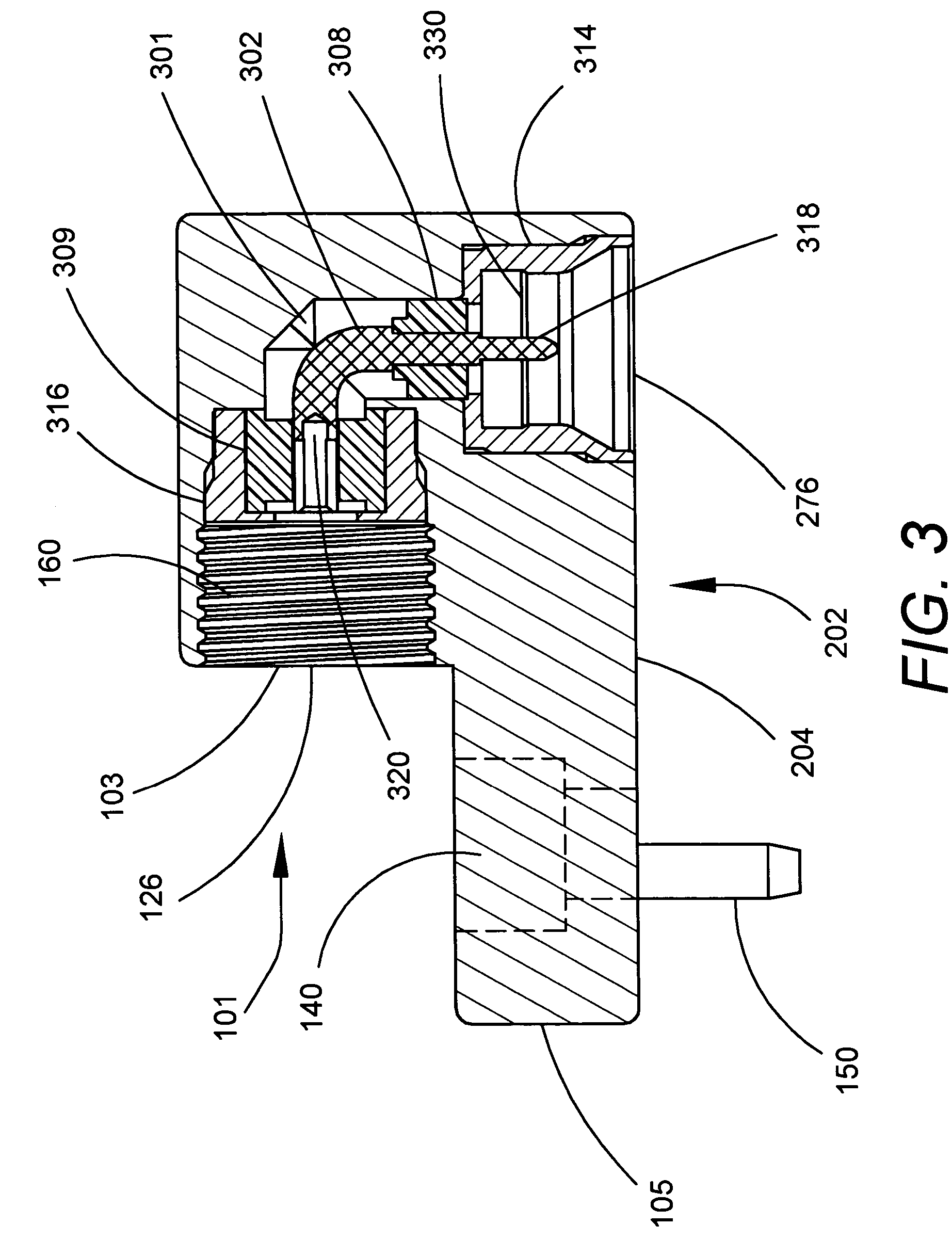
[0035]FIG. 1 is a perspective view of an eight-position, right-angle, coaxial cable-to-male, push-on, electrical connector 100. Hereinafter, “electrical connector” may also be referred to as “connector”. The connector 100 comprises a housing 105, preferably a metallic housing. The housing 105 has a first face 103 and a second face 204 (see FIG. 2). The plane of the second face 204 is at a right angle to the plane of the first face 103. Each position of the connector 100 comprises one cable port and one male port. The connector 100 has a cable side 101 at the first face 103 of the housing 105 and a male side 202 (see FIG. 2) at the second face 204 of the housing. As more fully explained hereinafter, a plurality of coaxial cables can be attached to cable ports on the cable side 101 of the connector 100, and plurality of female connectors can be attached to male ports on the male side 202 of the connector.

[0036]The connector 100 has a first set of eight (8) closely-spaced bores 111–118...


PUM


Abstract

A multi-port, electrical connector (100) includes a housing (105) having cable ports (122–128) for coaxial cables (421–428) on a cable side (101) of the housing and male push-on ports (271–278) for female connectors (801) on a male side (202). Each cable port has nonstandard internal threads (160). Each coaxial cable is terminated with a cable adapter (120). A coaxial cable-cable adapter combination is removably secured to each cable port by a clamp nut (130) having nonstandard external threads (660). Each coaxial cable-cable adapter combination is individually field replaceable. Another multi-port electrical connector (1000) includes a housing (1005) having male, push-on ports (1021–1028) on a male side (1001) of the housing and printed wiring board (PWB) ports (1171–1178) on a PWB side (1102). Each PWB port includes a straight PWB pin (1181–1188) for insertion into a hole in a PWB (1301).

Description

BACKGROUND OF THE INVENTION[0001]1. Field of the Invention[0002]This invention relates to electrical connectors, and more particularly to an electrical connector system having a plurality of push-on style interfaces and designed to connect a plurality of coaxial cables to a printed wiring board.[0003]2. Description of the Related Art[0004]Microwave connectors having a push-on style interface, such as a subminiature push-on (“SMP”) interface and a SMP-miniature (“SMPM”) interface, as described in MIL-STD-348A, are well known. Microwave connectors having a port with a push-on style interface designed to connect a coaxial cable to a printed wiring board (“PWB”) are well known. However, all such known microwave connectors having a push-on style interface are single-position connectors. When a plurality of coaxial cables are coupled to a PWB, a plurality of single-position connectors is needed. Disadvantageously, the plurality of coaxial cables cannot be uncoupled from the plurality of s...

Claims


Application Information

Patent Timeline
Patent Type & Authority Patents(United States)
IPC IPC(8): H01R12/00
CPCH01R24/52H01R9/0521H01R23/6873H01R2103/00H01R24/545H01R43/26
Inventor KOOIMAN, JOHN A.
Owner CORNING OPTICAL COMM LLC
Learn More