
Fluid mixing device

Inactive Publication Date: 2007-01-23
TROJAN TECH
View PDF24 Cites 15 Cited by
  • Summary
  • Abstract
  • Description
  • Claims
  • Application Information

AI Technical Summary

Benefits of technology

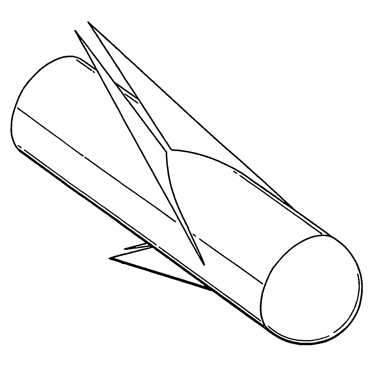
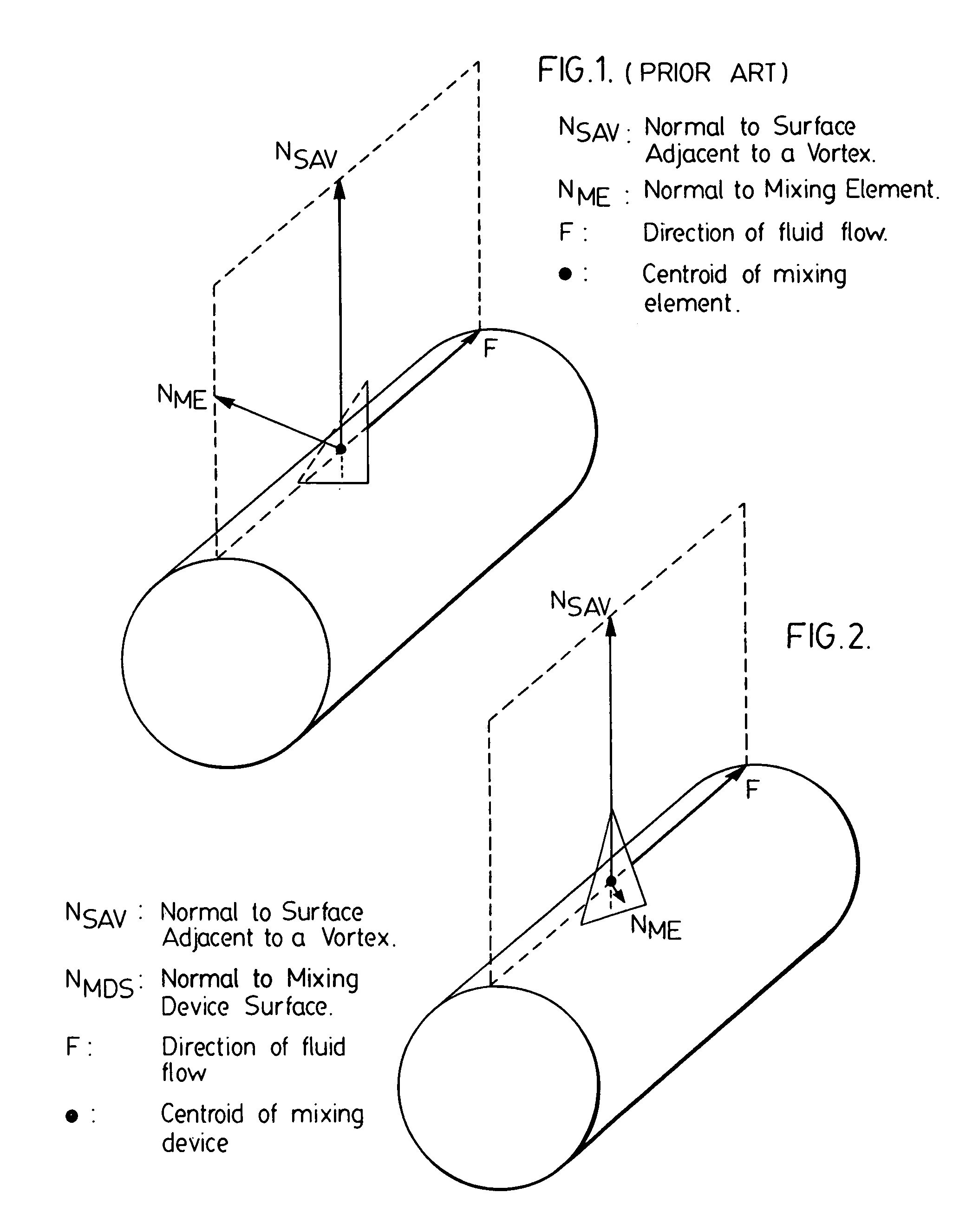
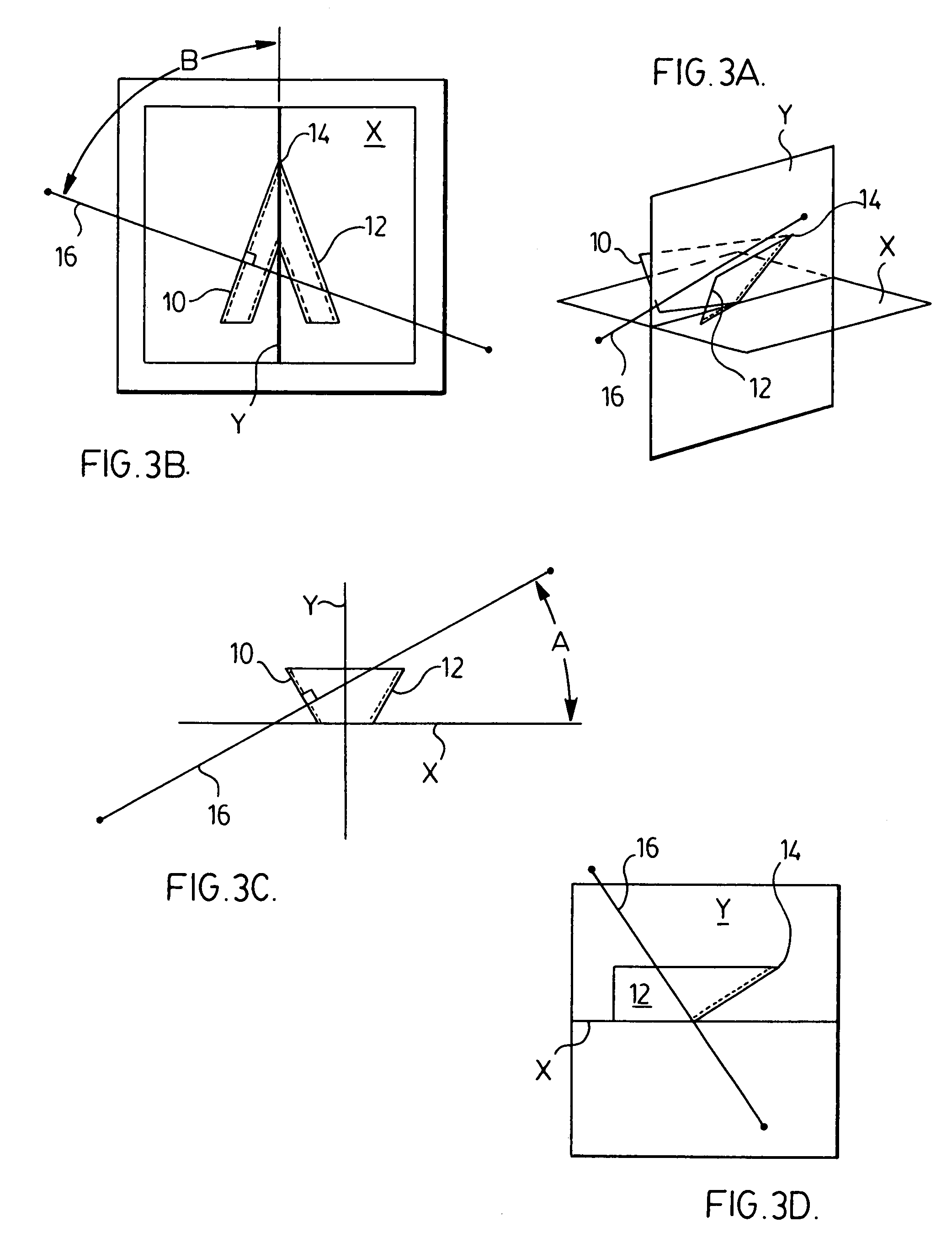
[0032]Thus, the present inventors have designed a novel fluid device having at least one mixing element oriented in a manner to achieve improved mixing of the fluid.
[0034]This novel orientation of the mixing element results in improved fluid mixing. When the fluid mixing device is employed in a fluid treatment system such as UV disinfection system the improved fluid mixing is manifested in an improvement of UV dose delivery of the system. Additionally, in various preferred embodiments of the present fluid mixing device, such improved fluid mixing is accompanied by a reduction in hydraulic head loss of fluid passing through the system.

Problems solved by technology

This necessarily results in a loss of fluid pressure, or fluid head in an open channel system.
This is very undesirable in UV disinfection systems, particularly those used to treat municipal wastewater, since the UV disinfection system typically is the last station of the multi-station treatment plant.
As such, wastewater entering the treatment plant typically suffers hydraulic head loss as it passes from station to station with the result that, when the wastewater reaches the UV disinfection system, there is not much room for further significant loss of hydraulic head.

Method used


Image

  • Fluid mixing device
  • Fluid mixing device
  • Fluid mixing device

Examples


Embodiment Construction

[0052]Throughout this specification, reference will be made to employment of the present fluid mixing device in fluid treatment systems such as fluid radiation treatment systems (e.g., UV disinfection systems). Those of skill in the art will recognize that, while the preferred embodiment of the present invention is a fluid radiation treatment system incorporating the present fluid mixing device, the scope of the invention is not to be so limited. Specifically, it is envisioned that the present fluid mixing device will have many applications outside the art of fluid radiation treatment systems.

[0053]As used throughout this specification, repeated reference is made to the term “normal”. In connection with a point on a planar surface, the term “normal” is intended to mean a line perpendicular to the tangent plane at that point on the surface. In connection with a point on a curved surface, the term “normal” is intended to mean a line perpendicular to the tangent plane at that point on ...


PUM


Abstract

A fluid mixing device comprising at least one mixing element specifically oriented with respect to the direction of fluid flow through the device. This novel orientation of the mixing element results in improved fluid mixing.

Description

CROSS-REFERENCE TO RELATED APPLICATION[0001]The present application claims the benefit under 35 U.S.C. §119(e) of provisional patent application Ser. No. 60 / 209,597, filed Jun. 6, 2000, the contents of which are hereby incorporated by reference.BACKGROUND OF THE INVENTION[0002]1. Field of the Invention[0003]In one of its aspects, the present invention relates to a fluid mixing device. In another of its aspects, the present invention relates to a method for mixing a fluid.[0004]2. Description of the Prior Art[0005]Mixing devices are known in the art and have been used to promote fluid turbulence—for example, to improve contact between elements in the flow path. Industrial applications of mixing are widely varied, and include heat exchange, reactor engineering and non-reactive blending.[0006]One specific area of reactor engineering where mixing has been used is in the design of fluid treatment devices, particularly fluid radiation treatment devices. A specific such fluid radiation tre...

Claims


Application Information

Patent Timeline
IPC IPC(8): C02F1/32B01F5/00B01F13/00C02F1/00
CPCB01F5/00B01F5/0618C02F1/006C02F1/325B01F13/0049B01F2005/0017B01F2005/0621C02F2301/024B01F2215/0052C02F2201/328B01F2005/0637B01F2025/913B01F25/4317B01F25/4316B01F25/431972B01F33/503B01F2101/305
Inventor BRUNET, ROBERT A. H.BUFFLE, MARC-OLIVIERCHIU, KUANG-PINGLU, DONGMINGTAGHIPOUR, FARIBORZ
Owner TROJAN TECH
Learn More