Ribbon takeup device and printer with ribbon takeup device

a take-up device and ribbon technology, applied in the direction of printing, inking apparatus, etc., can solve the problems of heavy load on the take-up axes, requiring a greater tensile force of the tension spring, and heavy load on the motor, so as to reduce the peak torque of the motor and be less costly

Inactive Publication Date: 2007-01-30
CITIZEN WATCH CO LTD
View PDF7 Cites 0 Cited by
  • Summary
  • Abstract
  • Description
  • Claims
  • Application Information

AI Technical Summary

Benefits of technology

[0025]It is an object of the present invention to solve the problems in the prior art, to reduce the peak torque of the motor used for the ribbon takeup mechanism, and to make the driving motor compact and less costly.
[0027]Varying this rotational driving torque ratio reduces the peak torque of the motor used in the ribbon takeup mechanism.
[0032]This configuration allows the elastic member and the motor to share the load of ribbon feeding and the load of ribbon feed claw switching, reduces the required motor torque, and makes it possible to employ a less powerful, less costly motor.
[0033]At a ribbon feeding time when the load of the ribbon takeup axes is light, only the elastic force of the elastic member, not the motor driving force, is used. At a ribbon feed claw switching time when the load of the ribbon takeup axes is heavy, the resultant force of the elastic force of the elastic member and the motor driving force is used. This configuration reduces the peak torque of the motor and makes it possible to employ a less powerful, less costly motor.
[0042]This present invention reduces the peak torque of the motor used for the ribbon takeup mechanism and makes it possible to employ a compact, less costly motor for driving.

Problems solved by technology

The problem here is that the ribbon takeup axes that have a heavy load require a greater tensile force of the tension spring.
Therefore, a greater tensile force of the tension spring is required and a heavy load is applied to the motor.
Another problem is that the motor drive efficiency becomes low because the motor drives the mechanism always under the load of the tensile force of the tension spring.
However, because a heavy load must be applied to the motor when the ribbon is switched, the motor requires a large driving torque and therefore a large motor is required.

Method used


Image

  • Ribbon takeup device and printer with ribbon takeup device
  • Ribbon takeup device and printer with ribbon takeup device
  • Ribbon takeup device and printer with ribbon takeup device

Examples


Embodiment Construction

[0060]A ribbon takeup device according to the present invention and a printer on which the ribbon takeup device is installed will be described in detail below with reference to the drawings.

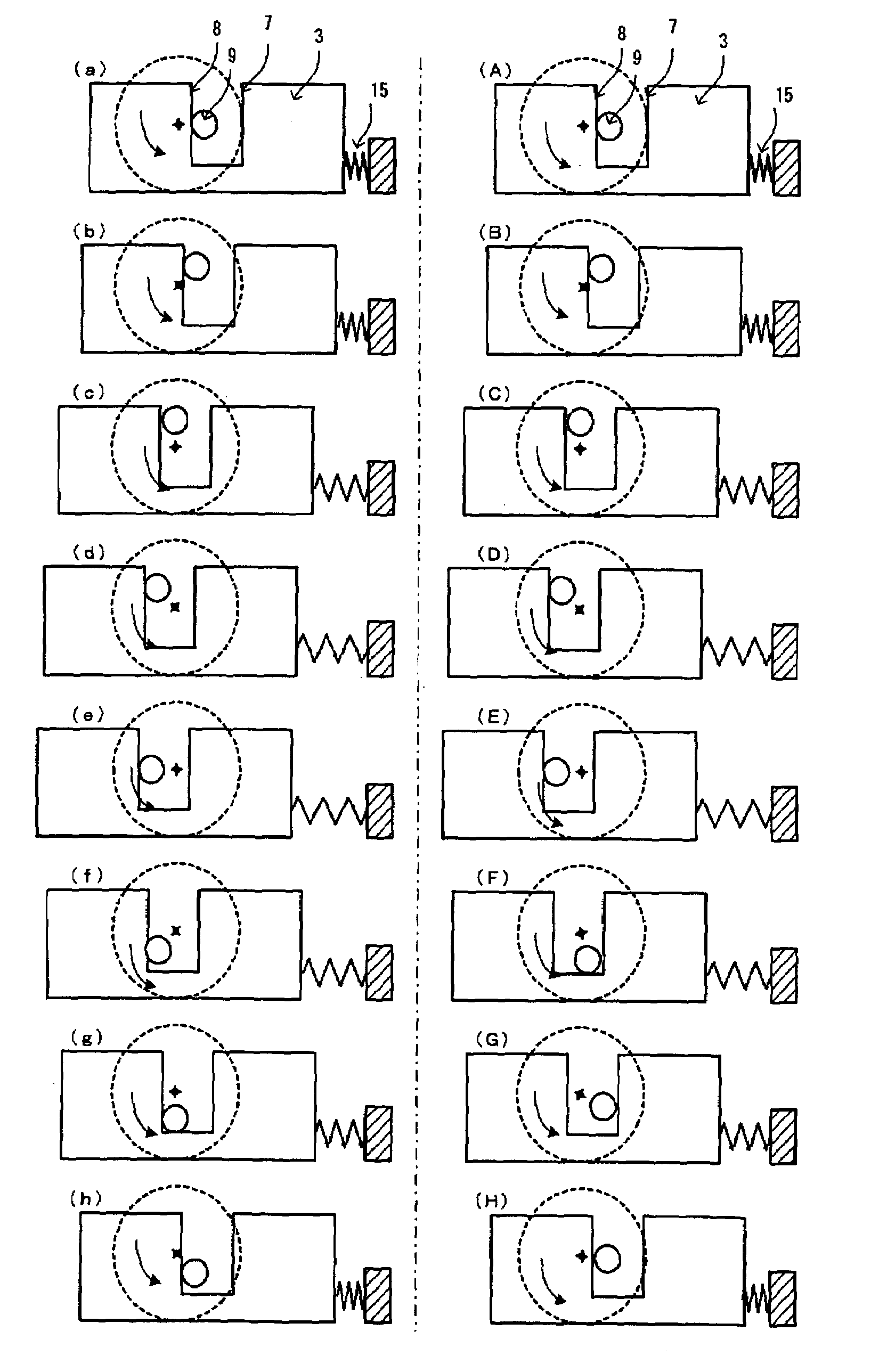
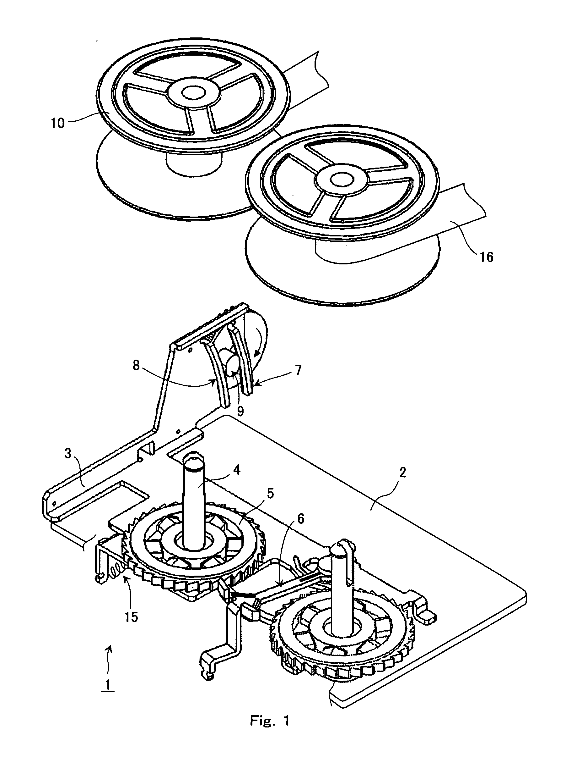
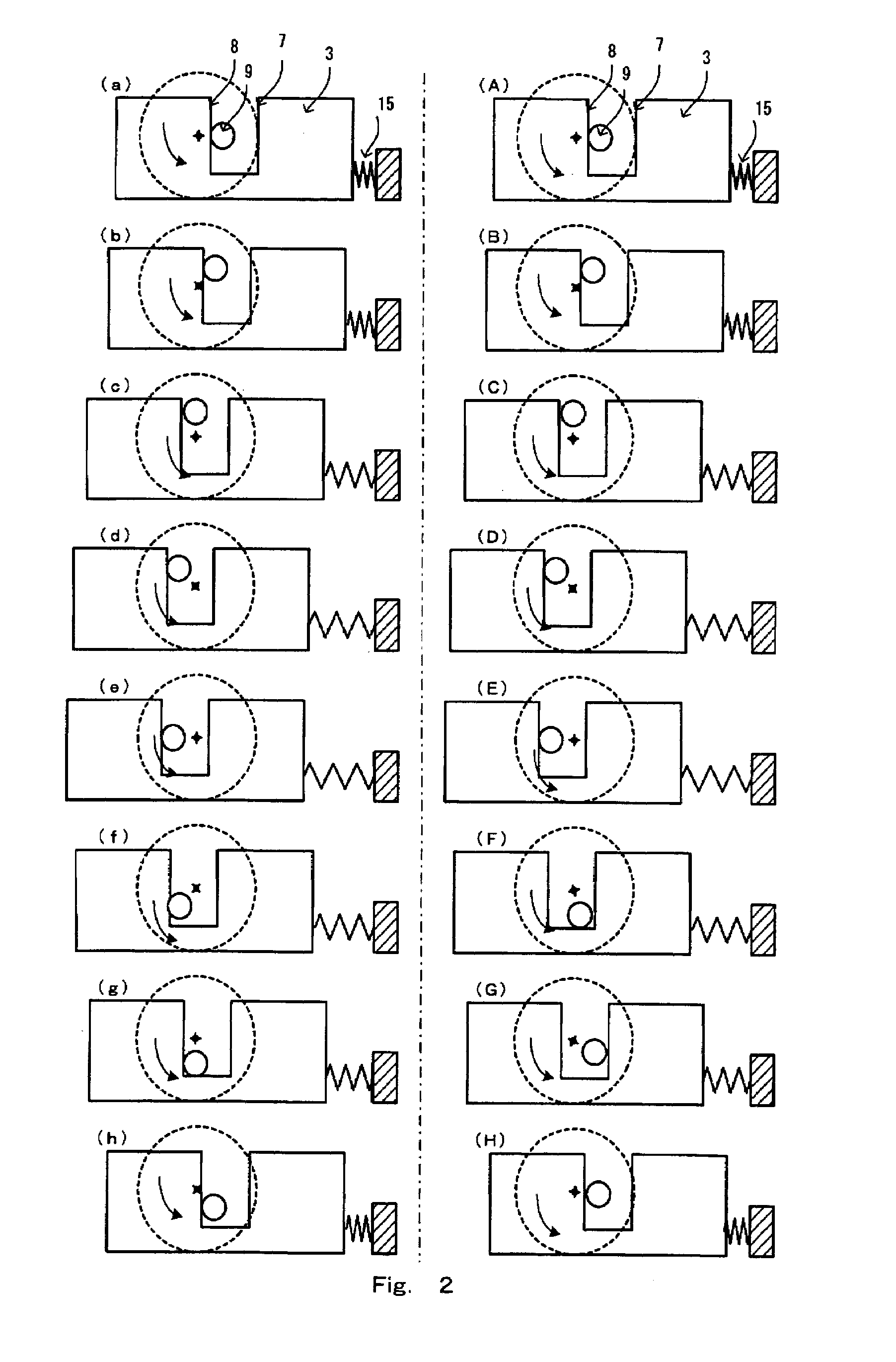
[0061]FIG. 1 is a general diagram showing a mechanism for taking up an inked ribbon by a ribbon takeup device according to the present invention.

[0062]Referring to FIG. 1, a ribbon takeup mechanism 1 has a pair of ribbon takeup axes 4, each with a ratchet wheel 5, on a ribbon frame 2. Ribbon spools 10, on which a ribbon 16 is wound, are mounted on this pair of ribbon takeup axes 4.

[0063]A slide member 3 is slidably installed on the ribbon frame 2, with an elastic member 15 such as a tension spring between the ribbon frame 2 and the slide member 3. A feed claw 6 is provided on the slide member 3. The feed claw 6 engages the ratchet wheel 5 to drive the ribbon takeup axes 4. The slide member 3 is similar in operation to the ribbon feed plate, shown in FIGS. 13 and 15, in that it drives the feed cla...


PUM


Abstract

The present invention reduces the peak torque of a motor used in a ribbon takeup mechanism and makes the motor, used for driving, smaller and less costly. A ribbon takeup device includes ratchet wheels (5) provided on ribbon takeup axes (4), a feed claw (6) that engages the ratchet wheels, a displacement member (9) driven and displaced by a motor (11) so that at least a linear displacement is given, a slide member (3) that moves the feed claw, and an elastic member (15). The configuration is that the elastic member engages the slide member that has the ribbon feed claw for taking up a ribbon and, with force applied to the slide member into one direction by the elastic member, a motor driving force is added to the slide member into the same direction as the direction in which the elastic member applies force. This configuration allows the elastic member and the motor to share the load of ribbon feeding and the load of ribbon feed claw switching, reduces the required motor torque, and makes it possible to employ a less powerful, less costly motor.

Description

BACKGROUND OF THE INVENTION[0001]1. Field of the Invention[0002]The present invention relates to the ribbon takeup device of an inked ribbon device and to a printer.[0003]2. Description of the Related Art[0004]For a ribbon takeup mechanism used in an inked ribbon device mounted on a small printer, some are known as mechanisms for taking up a ribbon such as a mechanism that uses the tensile force of a tension spring and a mechanism that uses the drive torque of a motor, are known (see Patent Document 1, Patent Document 2).[0005]FIG. 13 is a general diagram showing a mechanism that takes up an inked ribbon by the tensile force of a tension spring.[0006]Referring to FIG. 13, a ribbon takeup mechanism 101 has a pair of ribbon takeup axes 104, each with a ratchet wheel 105, on a ribbon frame 102. Ribbon spools 110, on which a ribbon 116 is wound, are mounted on this pair of ribbon takeup axes 104.[0007]A ribbon feed plate 103 is slidably installed on the ribbon frame 102, with a tension ...

Claims


Application Information

Patent Timeline
Patent Type & Authority Patents(United States)
IPC IPC(8): B41J33/18B41J33/14B41J33/48
CPCB41J33/14
Inventor TSUGARU, HIROYUKI
Owner CITIZEN WATCH CO LTD
Why Eureka
Try Eureka