

Fuel injection rate variable diesel fuel injection system and method for diesel engine
A diesel engine and injection system technology, applied in engine control, machine/engine, fuel injection control, etc., can solve problems such as not meeting the optimal requirements of the engine, and achieve the goal of reducing design difficulty, reducing driving peak torque, and improving reliability. Effect
- Summary
- Abstract
- Description
- Claims
- Application Information
AI Technical Summary
Problems solved by technology
Method used
Image

Examples
Embodiment 1
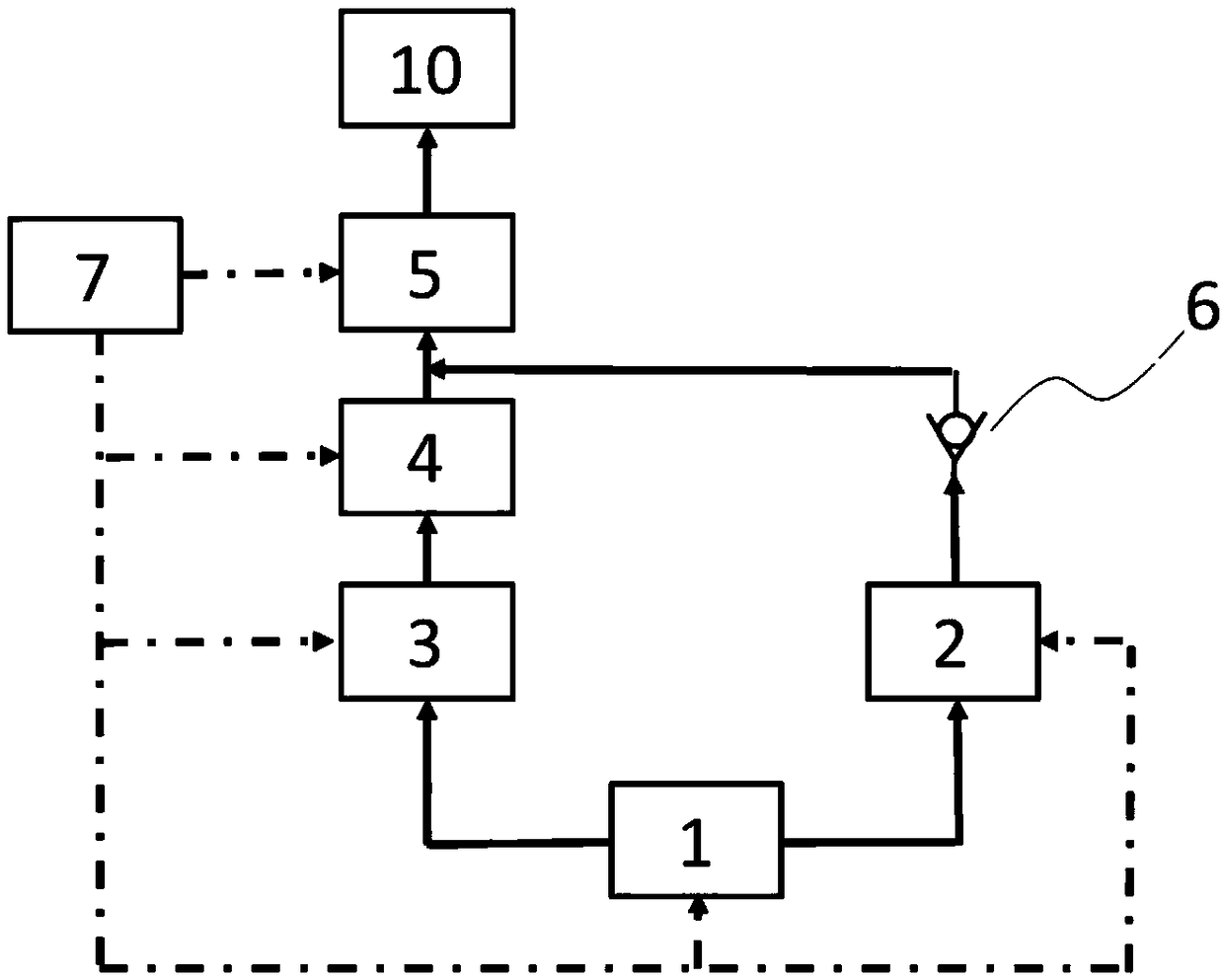
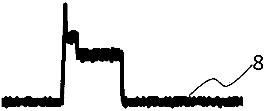
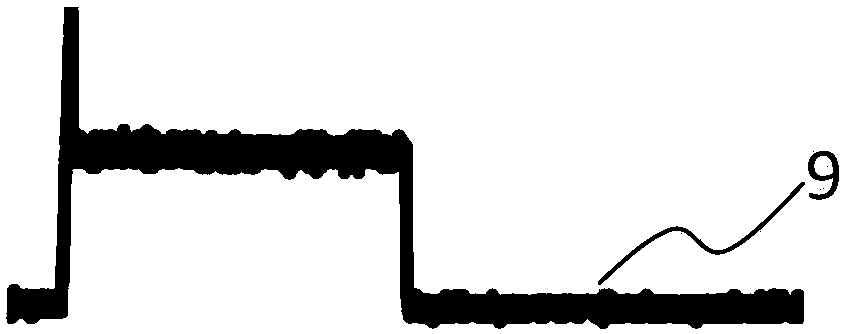
[0033] Embodiment 1: The low-pressure fuel rail 2 builds up a pressure of 500 bar under the action of the high-pressure oil pump 1, and the high-pressure fuel rail 3 builds up a pressure of 1000 bar under the action of the high-pressure oil pump 1. The electronic control unit ECU7 controls the electronically controlled fuel injector Ⅰ5 to open for 3000us, and electronic control after 2000us The unit ECU7 controls the electronic control injector Ⅱ4 to turn on for 1000us, and the electronic control unit ECU7 controls the electronic control injector Ⅰ5 and the electronic control injector Ⅱ4 to close simultaneously at 3000us.
Embodiment 2
[0034] Embodiment 2: The low-pressure fuel rail 2 builds up a pressure of 1200bar under the action of the high-pressure oil pump 1, and the high-pressure fuel rail 3 builds up a pressure of 2200bar under the action of the high-pressure oil pump 1. The electronic control unit ECU7 controls the electronically controlled fuel injector Ⅰ5 to open for 5000us, and electronic control after 3000us The unit ECU7 controls the electronic control injector Ⅱ4 to turn on for 2000us, and the electronic control unit ECU7 controls the electronic control injector Ⅰ5 and the electronic control injector Ⅱ4 to close at the same time at 5000us.
Embodiment 3
[0035] Example 3: The low-pressure fuel rail 2 builds up a pressure of 850bar under the action of the high-pressure oil pump 1, and the high-pressure fuel rail 3 builds up a pressure of 1600bar under the action of the high-pressure oil pump 1. The electronic control unit ECU7 controls the electronically controlled fuel injector Ⅰ5 to open for 4000us, and electronic control after 2500us The unit ECU7 controls the electronic control injector Ⅱ4 to turn on for 1500us, and the electronic control unit ECU7 controls the electronic control injector Ⅰ5 and the electronic control injector Ⅱ4 to close simultaneously at 4000us.
PUM
 Abstract
Description
Claims
Application Information