Variable-injection-rate injection system and method of dual-common-rail mechanical fuel injector for diesel engine

A mechanical fuel injection and injection system technology, applied in mechanical equipment, fuel injection control, machine/engine, etc., can solve problems such as not being able to meet the best requirements of the engine, reduce design difficulty, improve reliability, and achieve fuel consumption and emissions Effect

Pending Publication Date: 2018-12-18
FAW JIEFANG AUTOMOTIVE CO
View PDF4 Cites 1 Cited by
  • Summary
  • Abstract
  • Description
  • Claims
  • Application Information

AI Technical Summary

Problems solved by technology

[0005] During a single fuel injection process, the fuel injection pressure of the conventional common rail fuel injection system is constant, so that the shape of the main injection fuel injection rate of the electronically controlled f

Method used


Image

  • Variable-injection-rate injection system and method of dual-common-rail mechanical fuel injector for diesel engine
  • Variable-injection-rate injection system and method of dual-common-rail mechanical fuel injector for diesel engine
  • Variable-injection-rate injection system and method of dual-common-rail mechanical fuel injector for diesel engine

Examples


Embodiment 1

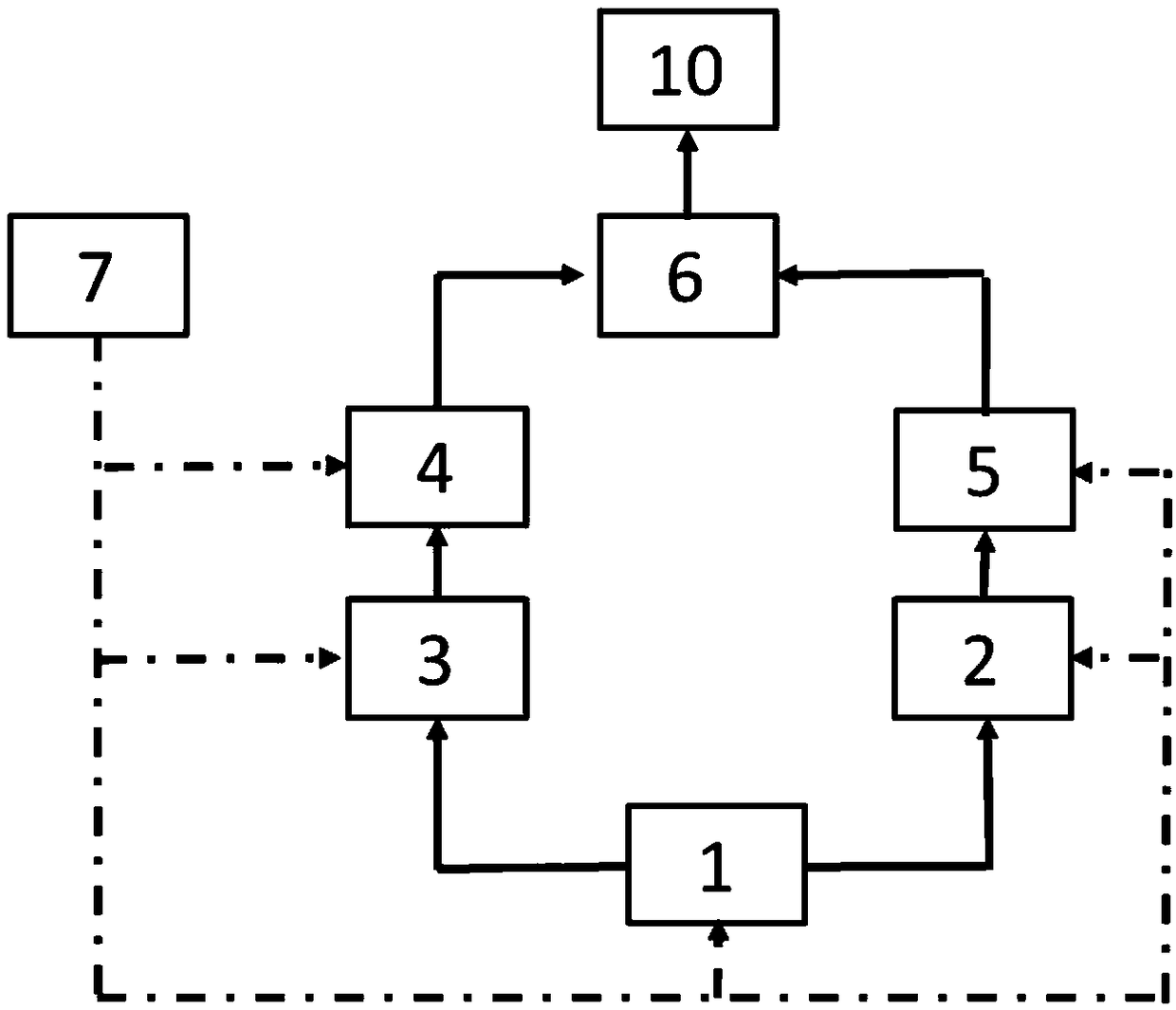
[0032] Embodiment 1: the low-pressure oil rail 2 establishes a pressure of 400 bar under the action of the high-pressure oil pump 1, and the high-pressure oil rail 3 establishes a pressure of 1000 bar under the action of the high-pressure oil pump 1. The electronic control unit ECU7 controls the electronically controlled fuel injector 15 to open it after 1000 us and close it. At the same time, the electronic control unit ECU7 electronically controlled fuel injector Ⅱ4 is turned on for 1000us and then turned off.

Embodiment 2

[0033] Embodiment two: the low-pressure oil rail 2 establishes a pressure of 1000 bar under the action of the high-pressure oil pump 1, and the high-pressure oil rail 3 establishes a pressure of 2400 bar under the action of the high-pressure oil pump 1. The electronic control unit ECU7 controls the electronically controlled fuel injector 15 to open it after 3000us and close it. At the same time, the electronic control unit ECU7 electronically controlled fuel injector Ⅱ4 is turned on for 2000us and then turned off.

Embodiment 3

[0034]Embodiment three: the low-pressure fuel rail 2 establishes a pressure of 700 bar under the action of the high-pressure oil pump 1, and the high-pressure oil rail 3 establishes a pressure of 1600 bar under the action of the high-pressure oil pump 1. The electronic control unit ECU7 controls the electronically controlled fuel injector 15 to open it after 2000 us and close it. At the same time, the electronic control unit ECU7 electronically controlled fuel injector Ⅱ4 is turned on for 1500us and then turned off.


PUM


Abstract

The invention discloses a variable-injection-rate injection system and method of a dual-common-rail mechanical fuel injector for a diesel engine. The system comprises a high-pressure fuel pump, a low-pressure fuel l rail, a high-pressure fuel rail, an electric control fuel injector I, an electric control fuel injector II, a mechanical fuel injector and an ECU; the mechanical fuel injector is arranged above an engine combustion chamber, the electric control fuel injector I is arranged in a pipeline between the low-pressure fuel rail and the mechanical fuel injector, the electric control fuel injector II is arranged in a pipeline between the high-pressure fuel rail and the mechanical fuel injector, and the ECU is connected with the high-pressure fuel pump, the low-pressure fuel rail, the high-pressure fuel rail, the electric control fuel injector I, the electric control fuel injector II and the mechanical fuel injector through wires. According to the variable-injection-rate injection system and method of the dual-common-rail mechanical fuel injector for the diesel engine, two fuel rails, a single cylinder, the two electric control fuel injectors and the mechanical fuel injector are adopted while the aim that the injecting pressure of the fuel injector is independent of the rotating speed of an engine is achieved, fuel injecting pressure low and high changes in the single-time fuel injection process can be achieved, and finally, the ideal, continuous and flexible variable oil injection rate can be achieved.

Description

technical field [0001] The invention belongs to the technical field of diesel injection systems for diesel engines, in particular to a variable injection rate injection system and method for dual common rail mechanical injectors for diesel engines. Background technique [0002] With the increasingly stringent emission regulations, the limit value of exhaust pollutants is getting lower and lower, especially in recent years, the limit value of diesel engine exhaust pollutants (mainly particles and nitrogen oxides) has reached the level of China V or China VI. In order to reduce the above two exhaust pollutants at the same time and make engine emissions meet the requirements of emission regulations, electronically controlled high-pressure common rail injection technology has become one of the implementation strategies to meet emission regulations. [0003] Electronically controlled high-pressure common rail injection technology refers to a closed-loop system composed of high-pr...

Claims


Application Information

Patent Timeline
IPC IPC(8): F02D41/38
CPCF02D41/3827F02D41/3836F02D2041/3881
Inventor 尹燕升戈非朱宏志张弛
Owner FAW JIEFANG AUTOMOTIVE CO
Why Eureka
Try Eureka