Opto-electronic encoder with three-dimensional scales

a three-dimensional scale and encoder technology, applied in the field of optoelectronic encoders, can solve the problems of only limited structural constraints, impeded the freedom of rolling devices, and sacrificing the optical utilization of phototransmitter output, etc., to achieve the effect of increasing the size of the joint or its complexity, and reducing the cost of operation

Inactive Publication Date: 2007-01-30
PAL ANADISH KUMAR
View PDF3 Cites 74 Cited by
  • Summary
  • Abstract
  • Description
  • Claims
  • Application Information

AI Technical Summary

Benefits of technology

[0006]The single-axis version of the present invention appears as a flat assembly in contrast with the three-layer assemblies of conventional opto-electronic encoders. As mentioned in the beginning, though the thickness of the cylindrical optical scale might seem negligible in comparison to the diameter of the same, it does function as the medium in which the beam of light travels from the phototransmitter to the opto-electronic sensor unit. This thickness cannot be made smaller than the diameter of the lens of the phototransmitter LED without sacrificing the optical utilization of the phototransmitter output. In the case of conventional opto-electronic encoders, the thickness of a planar optical scale is only limited by structural constraints. Theoretically, in this case, a light-opaque metallic film a few microns thick can also function as an effective optical barrier. This superficially planar placement of a phototransmitter and opto-electronic sensor with reference to a cylindrical optical scale makes the present construction more accessible for inspection and cleaning and, moreover, physically easier to disassemble.
[0007]The two- or three-axis form of the present invention consists of a spherical shell with multiple optical apertures distributed all over or near its surface, functioning together as the spherical optical encoder scale. With either air or some transparent material inside the spherical shell, the active surfaces of the mainly diametrically placed phototransmitters and opto-electronic sensors face each other / face one another. The basic operation of this novel encoder with a spherical optical scale is similar to the single-axis encoder of the present invention described hereinabove. To encode the three axes, three sets of opto-electronic devices are fitted at their logical places with regards to the mechanical structure of the encoder, each set consisting of a phototransmitter (a non-diffused LED) and an opto-electronic sensor unit. The multi-aperture spherical optical scale described hereinabove is set in motion by external forces by employing various means. The addition of a transparent material inside the spherical optical scale would reduce the driving power of the phototransmitter LED to almost by converging light from the phototransmitter on to the opto-electronic sensor unit in each set. Another possibility is to fill the spherical optical scale with a liquid opaque to the light of the transmitter LED and to put another light-weight, hollow and transparent spherical body permanently afloat on the liquid, the level of the liquid just below the active area of the opto-electronic receiver units. In this form the spherical optical scale responds to an impacting or distorting force by blocking the optical signal to all the opto-electronic sensor units—this in itself could generate a distinct signal to be used for various purposes. By making one half of the spherical optical scale heavier than the other, the center of gravity of the spherical optical scale becomes eccentric and makes a free-to-roll spherical optical scale which always settles in only one approximate position under the influence of gravity. This sums up the construction of not only a simple encoding apparatus, but also of a balancing-error-inputting device for a toy robot to remain upright and to mimic various human actions. This construction does away with the conventional frictionally revolving encoder discs, previously necessary for encoding, but which impeded the freedom of the rolling device. At the same time, it keeps the process of reading an encoded movement uncomplicated. The removal of the frictional elements also makes the present invention capable to be used with a prosthetic or robotic ball-and-socket joint as an integral three-axis, contact-less encoder, without increasing size of the joint or its complexity. To achieve this, the spherical encoder is joined to one end of a limb to become the ball of the joint, while all the opto-electronics are put into the socket part of the joint.
[0008]Accordingly, a principle object of the present invention is to simplify overall construction of single-, two- and three-axis encoders.
[0011]Another object of the invention is to devise a two- or three-axis encoder or coordinate input device with minimum frictional members and maximum user accessibility to all the primary optical elements.

Problems solved by technology

In the case of conventional opto-electronic encoders, the thickness of a planar optical scale is only limited by structural constraints.
This construction does away with the conventional frictionally revolving encoder discs, previously necessary for encoding, but which impeded the freedom of the rolling device.

Method used


Image

  • Opto-electronic encoder with three-dimensional scales
  • Opto-electronic encoder with three-dimensional scales
  • Opto-electronic encoder with three-dimensional scales

Examples


Embodiment Construction

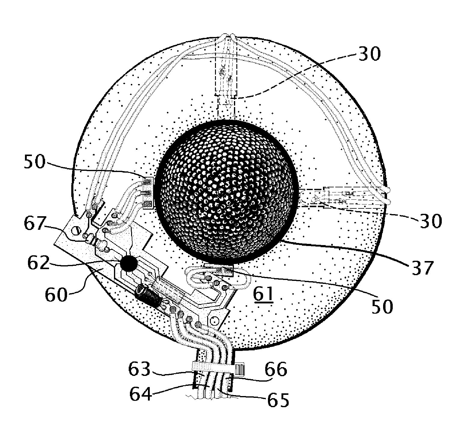
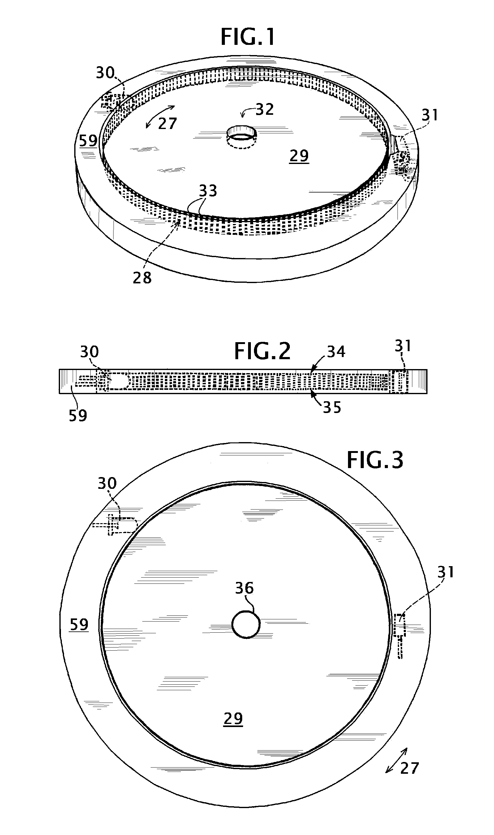
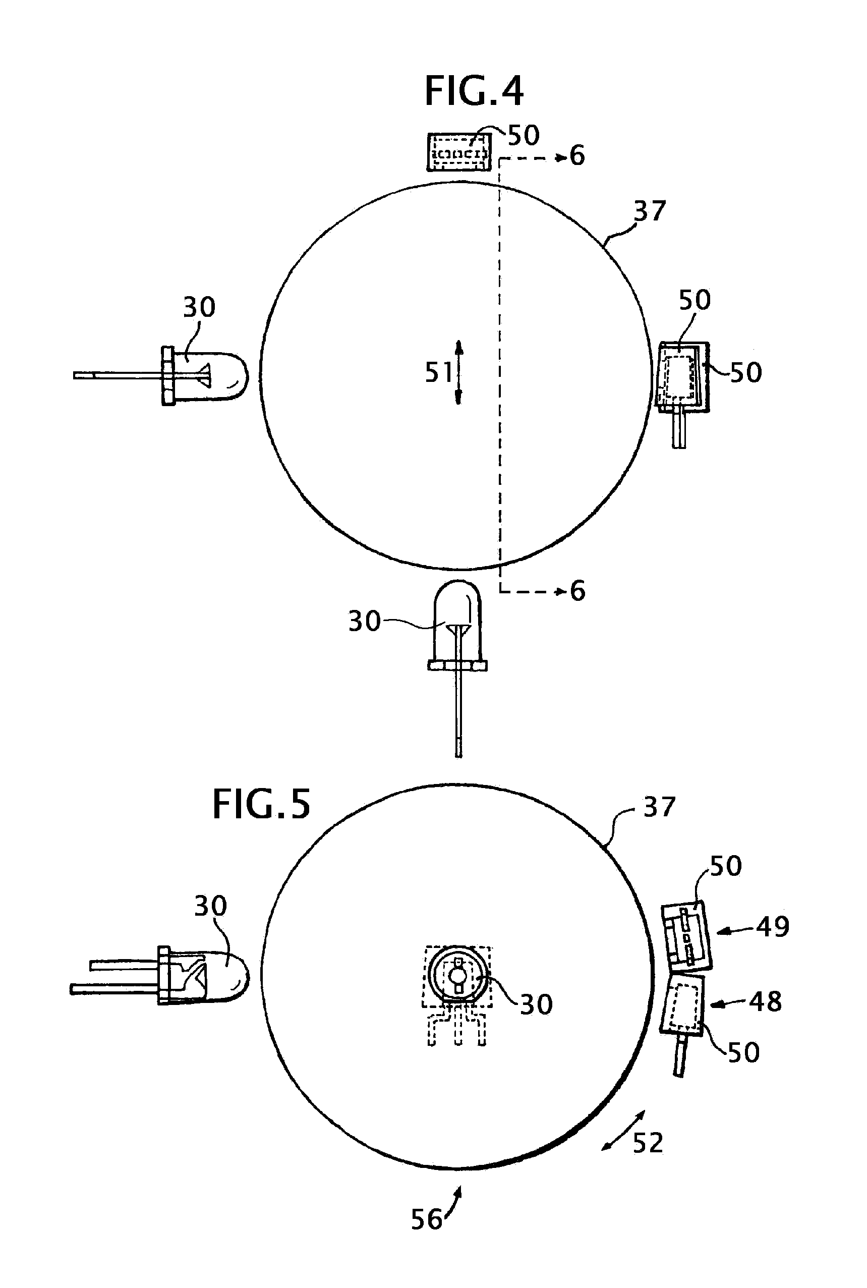
[0033]Referring to FIG. 1, an approximately parallel beam of light of certain wavelengths or bandwidth is emitted by a phototransmitter, non-diffused LED 30, towards the cylindrical surface 28 of encoder disc 29 made of a transparent material—a thermoplastic or glass. Said parallel beam of light would have crossed encoder disc 29 as secant lines. However, due to refraction in the medium which constitutes encoder disc 29, said beam angles towards central axis 32, comes out roughly from near opto-electronic sensor 31 and falls on the photosensitive part of it. Opto-electronic sensor 31 consists of twin photodiode, phototransistor or light-dependent resistor units with one pin from each unit connected together; the physical positioning of said units is one on the other with electrical connections pointing downwards, like opto-electronic sensor units 54 and 55 inside dual opto-electronic sensor 50 of FIG. 6. The travel of said beam of light through all circular and elliptical sectional ...


PUM


Abstract

A single-, two- or three-axis opto-electronic encoder, or error-inputting device, with an optical scale which is overall cylindrical, spherical or volumetric, as opposed to extant planar, circular optical scales; mostly parallel rays of light enter from the cylindrical or spherical surface of the scale, travel, with or without being modulated in intensity due to rotation / rotations of, or distortion / distortions in, the scale, along elliptical and / or circular sectional planes of the scale and exit to fall upon an obstructing opto-electronic sensor or a plurality of such sensors. A photo-transmissive spherical float on a photo-opaque liquid sealed inside a spherical optical scale, moving vertically under the influence of an external force, upwardly displacing the photo-opaque liquid to block the light that enters the spherical optical scale from reaching any of the opto-electronic sensors, produces a distinct electronic condition for auxiliary use in addition to or conjunction with encoder or error-inputting device output or outputs.

Description

BACKGROUND OF THE INVENTIONThe present invention is directed to the field of opto-electronic encoders with digital- or analogue-coded output or outputs.[0001]In the related field, opto-electronic encoder devices essentially consist of an optical barrier, systematic removal of that barrier does encoding of a movement linked to the optical barrier. Documentation of pioneering work finds place in U.S. Pat. Nos. 2,537,427, 2,685,082 and 2,944,157. All of these patents have a rotatory disc with numerous radial apertures to allow light from a phototransmitter to pass. The thickness of the disc with coded scale was only governed by the strength of material with which it was fabricated. The thinnest possible discs became desirable, as the electrical light-producing methods were not very efficient. Their low efficiency and limited filament life marked incandescent lamps. Running them only at very low illumination levels could make them longer lasting. Initial light-emitting diodes (LEDs) too...

Claims


Application Information

Patent Timeline
Patent Type & Authority Patents(United States)
IPC IPC(8): G01D5/34G09G5/08
CPCG01D5/347G01D5/34G01D2205/95
Inventor PAL, ANADISH KUMAR
Owner PAL ANADISH KUMAR
Why Eureka
Try Eureka