Magnetic transfer apparatus

Inactive Publication Date: 2007-01-30
FUJIFILM HLDG CORP +1
View PDF5 Cites 6 Cited by
  • Summary
  • Abstract
  • Description
  • Claims
  • Application Information

AI Technical Summary

Benefits of technology

[0012]Therefore, it is an object of the present invention to solve the problems encountered in the prior art and to provide a magnetic tra

Problems solved by technology

However, the latter case of vertically conveying the slave medium suffers from the disadvantages such as dropping of the slave medium during conveyance, and penetration of dust into a gap between the contact surfaces of the slave medium and the master carrier in addition to above-mentioned positioning.
However, since the central opening of the slave medium is only hung around the slave

Method used


Image

  • Magnetic transfer apparatus
  • Magnetic transfer apparatus
  • Magnetic transfer apparatus

Examples


Example

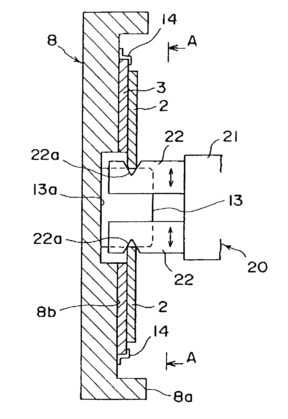
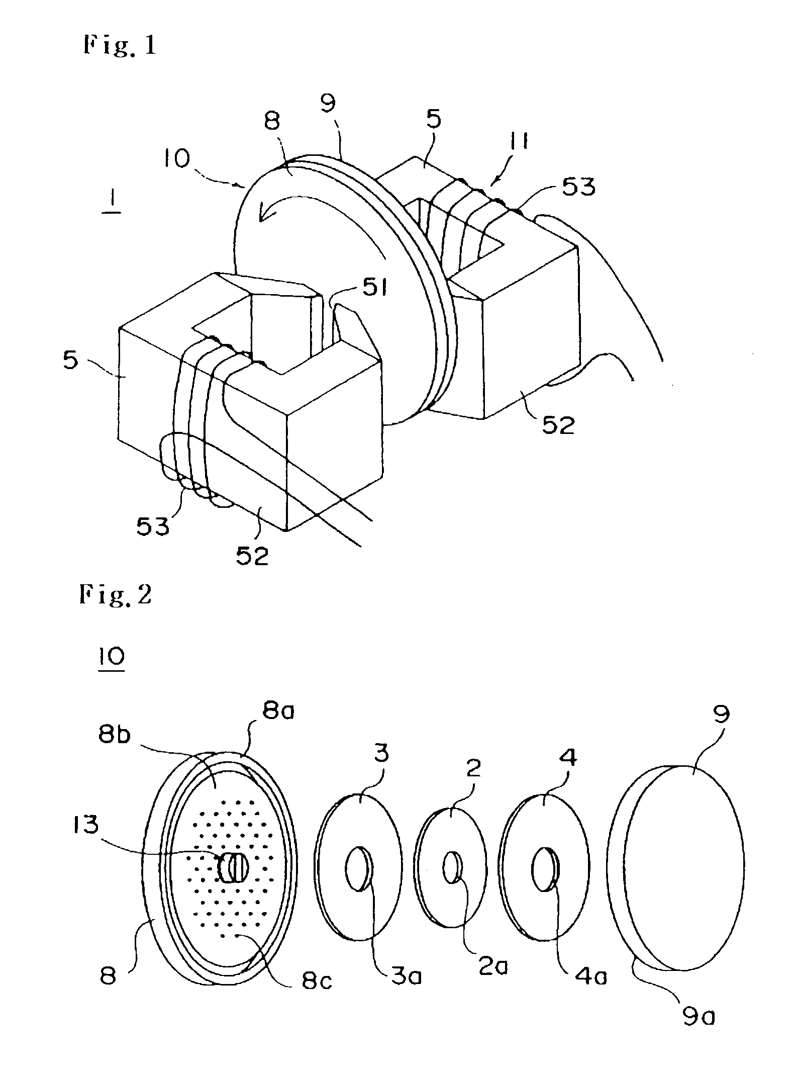
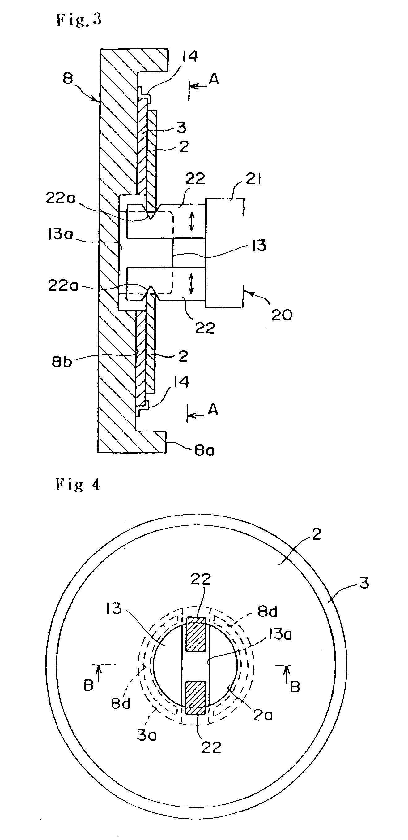
[0022]Now, a preferred embodiment of a magnetic transfer apparatus of the present invention will be described below with reference to the accompanying drawings. In FIG. 1, there is shown a perspective view of main parts showing a transfer state of the magnetic transfer apparatus according to an embodiment of the present invention. An exploded perspective view of the holder is shown in FIG. 2. A cross-section showing a feeding state of a slave medium is seen in FIG. 3, and a sectional front view of main parts taken along a line of A—A of FIG. 3 is shown in FIG. 4. Further, FIG. 5 shows a cross-section of main parts taken along a line of B—B of FIG. 4.

[0023]By use of a magnetic transfer apparatus 1 shown in FIGS. 1 and 2, master carriers 3 and 4, which have transfer patterns corresponding to servo signals, come into close contact with both recording surfaces of a slave medium 2 (magnetic recording medium), to which a magnetic field for transfer is applied, thus performing magnetic tra...


PUM


Abstract

Disclosed is a magnetic transfer apparatus capable of performing good magnetic transfer, including a holder for accommodating a master carrier with transfer patterns corresponding to transfer information, a slave-feeding unit for feeding a slave medium with a magnetic recording part to be transferred to the master carrier, and a magnetic field application unit for applying a magnetic field in a state that the slave medium is in close contact with the master carrier, wherein the holder is provided with a slave holding shaft for positioning a central opening of the slave medium at a central portion thereof, and an inner diameter of the central opening of the slave medium is set to be smaller than that of a central opening the master carrier, and the slave-feeding unit holds an inner diameter portion of the slave medium. The inner diameter portion of the slave medium fed to the master carrier is sucked by use of suction grooves, and the slave medium is preferably brought into temporary contact with the master carrier.

Description

BACKGROUND OF THE INVENTION[0001]1. Field of the Invention[0002]The present invention relates to a magnetic transfer apparatus for use in performing magnetic transfer from a master carrier having patterns corresponding to transfer information to a slave medium having a magnetic recording part, and in particular, to a magnetic transfer apparatus capable of accurately feeding the slave medium to the master carrier held in a holder.[0003]2. Description of the Prior Art[0004]Generally, a master carrier (patterned master) for magnetic transfer comprises transfer patterns such as servo signals in the form of surface irregularities or embedded structure, with at least a soft magnetic layer on a surface layer. Such a master carrier comes into close contact with a slave medium having a magnetic recording part, and a magnetic field for transfer is applied, whereby magnetic patterns corresponding to information carried on the master carrier are transferred to and recorded on the slave medium. ...

Claims


Application Information

Patent Timeline
IPC IPC(8): G11B5/86G11B23/03
CPCG11B5/865G11B5/86
Inventor KAMATANI, AKITO
Owner FUJIFILM HLDG CORP
Why Eureka
Try Eureka