Master carrier for magnetic transfer

a master carrier and magnetic transfer technology, applied in the direction of maintaining head carrier alignment, nanoinformatics, instruments, etc., can solve the problems of reducing reliability, signal quality, and non-magnetic transfer, so as to prevent the reduction of increase the recording loss, and improve the quality of the transferred signal

Inactive Publication Date: 2005-06-21
FUJIFILM HLDG CORP +1
View PDF6 Cites 25 Cited by
  • Summary
  • Abstract
  • Description
  • Claims
  • Application Information

AI Technical Summary

Benefits of technology

[0052]According to the master carrier of the present invention, each land in the aforementioned land / groove pattern has four round corners whose radius is from 1% through 47% of the width of a data track. Therefore, the master carrier of the present invention is capable of enhancing the quality of transferred signals by a reduction in recording loss, also enhancing durability by the prevention of damage to the pattern, and preventing poor transfer.
[0058]Furthermore, the fourth master carrier of the present invention is equipped with a pattern having a shape determined in view of the influence of a demagnetizing field. In this case, a desired magnetization pattern can be recorded with a high degree of accuracy on a magnetic recording medium. Since a desired magnetization pattern is recorded with high fidelity on a magnetic recording medium, information based on the magnetization pattern can be accurately reproduced. Particularly, in the case where the information is a serve signal, accuracy of tracking is enhanced.

Problems solved by technology

If the contact between the two is poor, regions where magnetic transfer is not performed will occur.
If magnetic transfer is not performed, missing signals occur in the magnetic information transferred to the slave medium and therefore the signal quality is reduced.
In the case where a signal recorded is a servo signal, the tracking function cannot be sufficiently obtained, and consequently, there is a problem that reliability will be reduced.
As a result, it has been found that there are cases where depending on the generating condition for the master carrier, the signal quality is inferior to the signal quality in the case of a conventional method in which signals are recorded directly on the slave medium by a magnetic head, etc.
It has also been found that the chipped corner produces dust particles which will cause the quality degradation of transferred signals.
As a result, it has been found that if the radius R of the rounded corner is increased, the rounded corner causes recording loss to occur in a transfer field applied when magnetic transfer is performed with the master carrier and the slave medium held in direct contact with each other.
Because of this, the magnetization pattern formed on the slave medium becomes incomplete, and distinct signals cannot be recorded.
From this fact it has been found that (1) the corner of the land in the land / groove pattern chips, (2) the chipped pieces remain on the land / groove pattern, and (3) missing signals occur due to poor magnetic transfer.
If dust particles are present on the intimate contact portion, stable magnetic transfer cannot be performed and, in addition, there is a possibility that the master carrier or slave medium itself will be damaged.
The separated portion on the intimate contact portion reduces the quantity of transferred signals and degrades the durability of the master carrier.
Because of this, if magnetic transfer is repeated a great number of times, the magnetic layer formed on the substrate will undergo wear, abrasion, separation, chipping, and edge deformation during the aforementioned steps.
Consequently, there is a problem that (1) the shape of a pattern to be transferred will change and the quality of transferred signals will be reduced, (2) wear powder on the intimate contact portion will cause missing signals and reduce the quality of transferred signals, and (3) the durability of the master carrier will be degraded.
Furthermore, dust particles adhere to the direct contact portion between the magnetic layer and the slave medium and cause scores to occur in the magnetic layer.
Thereafter, poor contact occurs between the master carrier and the slave medium.
Thus, it becomes difficult to perform stable magnetic transfer repeatedly.
Particularly, in the case where information to be transferred is a servo signal, tracking performance is reduced and reliability is reduced.

Method used


Image

  • Master carrier for magnetic transfer
  • Master carrier for magnetic transfer
  • Master carrier for magnetic transfer

Examples


first embodiment

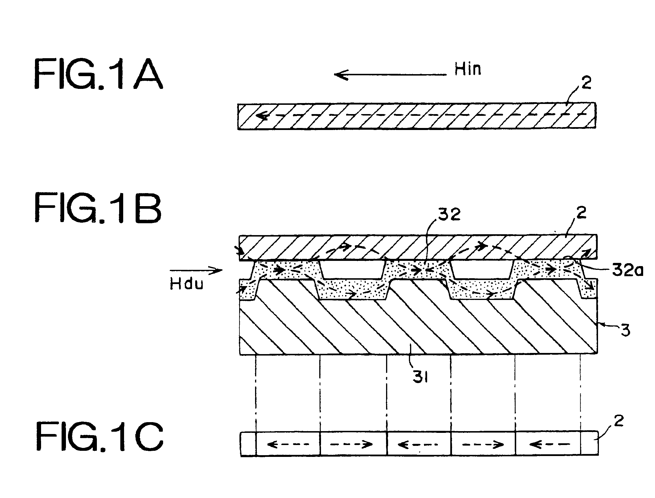
[0067]Referring to FIGS. 1 and 2, there is shown a magnetic transfer method using a master carrier constructed according to the present invention. The magnetic transfer method uses in-plane recording, as shown in FIG. 1. Note in FIGS. 1 and 2 that the dimensions of each part are shown at a ratio differing from the actual dimensions.

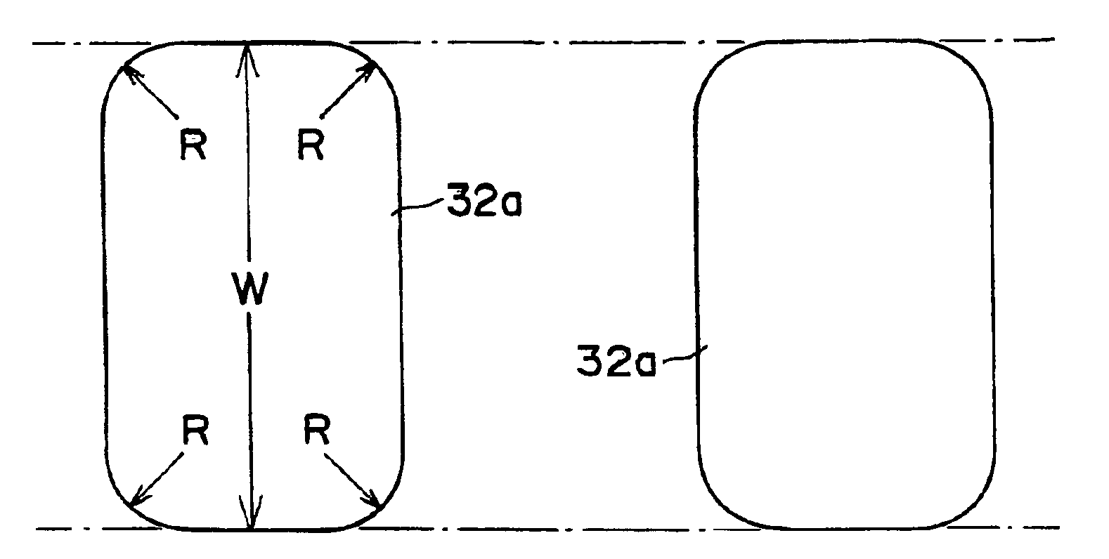
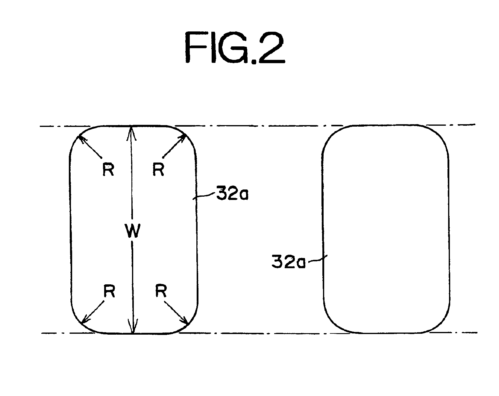
[0068]The magnetic transfer method using in-plane recording will be outlined. As shown in FIG. 1A, an initializing field Hin is first applied to a slave medium 2 in one direction along the direction of a data track on a disk to perform initial magnetization (DC demagnetization). Then, as shown in FIG. 1B, the slave surface (magnetic recording portion) of the slave medium 2, and the top surface of the land pattern 32a of an information carrying surface consisting of a soft magnetic layer 32 (magnetic material) coated on a microscope land / groove pattern on the substrate 31 of a master carrier 3, are brought physical contact with each other. In the state of ...

second embodiment

[0113]In the case of the second embodiment shown in FIG. 3, the reinforcement portions 41c are arranged on both sides of the land 41a of the substrate 41 and are formed into the shape of a narrow width protrusion so that they become coplanar with the land 41a. By the reinforcement portions 41c, the magnetic land layer 42a is buried in the groove region formed in the land 41a.

[0114]For the master carrier 40 mentioned above, the substrate 41 with a microscopic land / groove pattern consisting of lands 41a, grooves 41b, and reinforcement portions 41c is first generated as shown in FIG. 4A. The land / groove pattern with different depths can be formed, for example, by multistage exposure and etching. The substrate 41 can be generated by a master ring employing the land / groove pattern.

[0115]Next, as shown in FIG. 4B, the magnetic layer 42 is formed on the substrate 41 to a predetermined thickness with a soft magnetic material by vacuum film forming means such as vacuum evaporation, sputteri...

third embodiment

[0124]A magnetic transfer method according to the present invention will hereinafter be described in detail. Initially, a description will be given of a master carrier, which is employed for magnetic transfer, and a magnetic recording medium, which is a slave medium to which predetermined information is transferred magnetically from the master carrier.

[0125]FIG. 6 shows the cross section of a magnetic recording medium 51 and a master carrier 54. The magnetic recording medium 51 is a magnetic disk for longitudinal recording and has a magnetic layer (recording-reproducing layer) 53 on a base 52. In FIG. 6, the recording-reproducing layer 53 is provided on only one side of the base 52. However, recording-reproducing layers may be provided on both sides of the base 52, respectively. Note that the base 52 may be a hard substrate or flexible substrate.

[0126]The master carrier 54 is formed into a disk shape and equipped with a substrate 55 and a soft magnetic layer 56. The surface of the s...


PUM

PropertyMeasurementUnit
coercive fieldaaaaaaaaaa
widthaaaaaaaaaa

Abstract

A master carrier for magnetic transfer is equipped with a substrate having a land / groove pattern. The land / groove pattern is formed from a magnetic material and corresponds to information that is transferred to a magnetic recording disk. Each land in the land / groove pattern has four round corners whose radius is from 1% through 47% of the width of a data track on the disk.

Description

BACKGROUND OF THE INVENTION[0001]1. Field of the Invention[0002]The present invention relates to a master carrier for magnetic transfer carrying information that is transferred magnetically to a slave medium.[0003]2. Description of the Related Art[0004]In a magnetic transfer method, the surface of the substrate of a master carrier, coated with a magnetic material having a “land / groove” pattern that corresponds to information to be transferred, is brought into intimate contact with the surface of a slave medium having a magnetic recording portion. In this state, a transfer field is applied, and a magnetization pattern corresponding to information (for example, a servo signal) carried by the master carrier is transferred and recorded on the magnetic recording portion of the slave medium. Such a magnetic transfer method is disclosed, for example, in Japanese Unexamined Patent Publication Nos. 63(1988)-183623, 10(1998)-40544, and 10(1998)-269566.[0005]The master carrier that is used for...

Claims


Application Information

Patent Timeline
Patent Type & Authority Patents(United States)
IPC IPC(8): G11B5/86G11B5/82G11B5/596
CPCB82Y10/00G11B5/865G11B5/82G11B5/743G11B5/59633G11B5/86
Inventor NISHIKAWA, MASAKAZUYASUNAGA, TADASHINIITSUMA, KAZUHIRO
Owner FUJIFILM HLDG CORP
Why Eureka
Try Eureka