Transfer apparatus for transferring an image of a developer in a printer and method for calibrating the heating system thereof

a technology of transfer apparatus and developer, which is applied in the direction of optics, instruments, electromagnetography/magnetography, etc., can solve the problem of decreasing the thickness of the image-bearing medium, and achieve the effect of improving the known transfer apparatus and roughly maintaining the quality of the transfer step

Inactive Publication Date: 2010-10-05
OCE TECH
View PDF14 Cites 4 Cited by
  • Summary
  • Abstract
  • Description
  • Claims
  • Application Information

AI Technical Summary

Benefits of technology

[0006]An object of the present invention is to improve the known transfer apparatus such that the quality of the transfer step roughly remains constant over the entire life of the image-bearing medium.
[0008]The ability to obtain a target temperature in the transfer zone ensures that the quality of the transfer step is improved over the entire life of the image-bearing medium. Indeed, after a large number of print cycles, the thickness of the image-bearing medium decreases, due to wear. This fact renders the control of the temperature in the transfer zone particularly important. A target temperature in the transfer zone is attainable, in response to the signal indicative of the sensed basis temperature and based on a pre-established relationship between the power supplied to the heating device and a temperature difference between a temperature in the transfer zone and the basis temperature. The value of the target temperature in the transfer zone is known beforehand and is a temperature that leads to optimum results of the transfer step. The presence of the pressure member renders the placement of a temperature sensor in the transfer zone for measuring the temperature in the transfer zone during printing operation for straightforward feed-back control impracticable. With the signal indicative of the sensed basis temperature and the pre-established relationship between the power supplied to the heating device and a temperature difference between a temperature in the transfer zone and the basis temperature, the controller is able to determine a target temperature difference between the target temperature in the transfer zone and the basis temperature. Based on said determined target temperature difference, and in response to the signal indicative of the sensed basis temperature, the power supplied to the heating device is adjustable to obtain the target temperature in the transfer zone.
[0009]According to an embodiment of the present invention, the heating device is provided with a displacing device that moves the heating device from a first position to a second position, the first and second positions being suited for establishing the relationship between the power supplied to the heating device and the temperature difference between the transfer temperature in the transfer zone and the basis temperature. The displacement of the heating device renders possible the determination of the temperature in the transfer zone, since in the second position, the presence of the pressure member does not hinder the determination of the temperature in the transfer zone anymore.

Problems solved by technology

Indeed, after a large number of print cycles, the thickness of the image-bearing medium decreases, due to wear.

Method used


Image

  • Transfer apparatus for transferring an image of a developer in a printer and method for calibrating the heating system thereof
  • Transfer apparatus for transferring an image of a developer in a printer and method for calibrating the heating system thereof
  • Transfer apparatus for transferring an image of a developer in a printer and method for calibrating the heating system thereof

Examples


second embodiment

[0065]As stated above, during the calibration procedure, while temperatures differences ΔT1 and ΔT2 are measured, the transfer drum is rotated at a “calibration speed.” In the method, the calibration speed may be larger than the normal printing speed, for example twice the normal printing speed. In this case, the temperature TNIP in the nip in normal conditions is the temperature TK measured by the sensor 70 after the nip 60, corrected by a certain proportionality factor. This is due to the fact that the calibration speed differs from the normal printing speed. Hence, the amount heat received by unity of surface of image-bearing surface depends on the rotation speed of the drum 12, which influences said proportionality factor.

[0066]During a printing operation, the temperature sensor 50 transmits at regular intervals a signal to the controller 64 indicative of the basis temperature TBASIS. In order to achieve proper fusing, a certain constant target temperature TNIP must be achieved ...

third embodiment

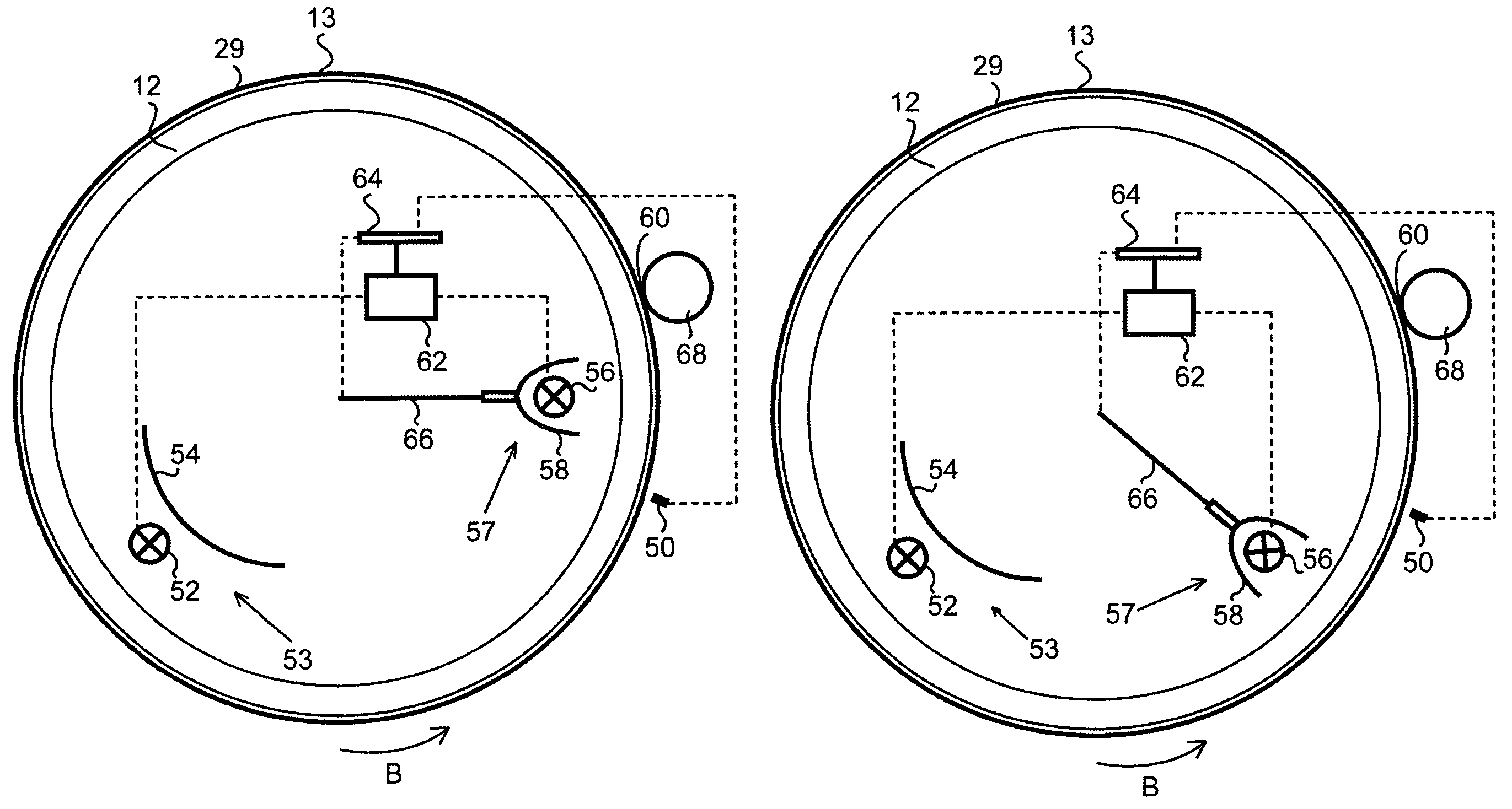
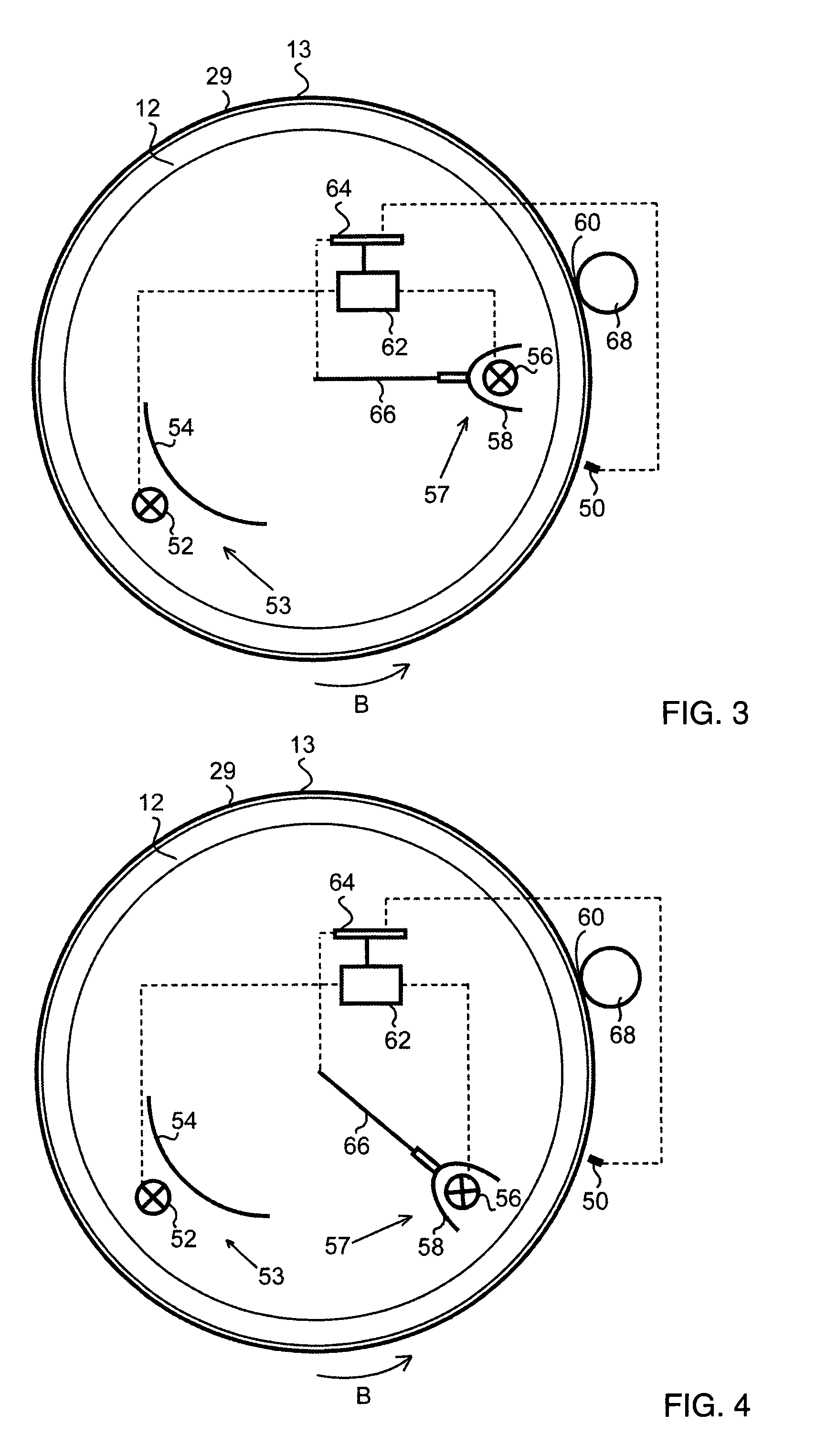
[0069]In the third embodiment, shown in FIG. 11, the transfer apparatus includes a pressure roll 68 for pressing the image-bearing medium 13 against the image receiving medium in a transfer zone 60, a heating device 57 provided with a displacing device 66, an electrical power supply device 62 supplies electrically the heating device 57 and a controller 64 that controls the electrical power supply device 62. The displacing device 66 is suited for moving part of or all of the heating device 57 from a first position to a second position. The displacing device 66 may be controlled by the controller 64. The displacing device 66 is for example a rotation device adapted to cause the heating device 57 to rotate around an axis perpendicular to the plane of the figure and parallel to the drum axis. With such a rotation device 66, the heating device may be rotated from a first position, shown in FIG. 12A to a second a second position, shown in FIG. 12B. The transfer apparatus further includes ...


PUM


Abstract

A transfer apparatus for transferring an image of a developer from an image-bearing medium onto an image receiving medium in a transfer zone includes a heating device that heats the image-bearing medium, an adjustable power supply device that supplies electrical power to the heating device, a first temperature sensor for sensing a basis temperature in the vicinity of the image-bearing medium away from the transfer zone and for transmitting to a controller a signal indicative of the basis temperature. The controller is adapted to adjust the power supplied by the power supply device to the heating device to obtain a target temperature in the transfer zone, in response to the signal indicative of the sensed basis temperature and based on a pre-established relationship between the power supplied to the heating device and a temperature difference between a temperature in the transfer zone and the basis temperature.

Description

CROSS-REFERENCE TO RELATED APPLICATIONS[0001]This nonprovisional application claims priority under 35 U.S.C. §119(a) on Patent Application No. 06112324, filed in Europe on Apr. 6, 2006, the entirety of which is incorporated herein by reference.BACKGROUND OF THE INVENTION[0002]1. Field of the Invention[0003]The present invention relates to a transfer apparatus for transferring an image of a developer from an image-bearing medium onto an image-receiving medium. The transfer apparatus includes a pressure member that presses the image receiving medium against the image-bearing medium in a transfer zone, a heating device that heats the image-bearing medium, an adjustable power supply device that supplies electrical power to the heating device, and a first temperature sensor that senses a basis temperature in the vicinity of the image-bearing medium away from the transfer zone and transmits a signal indicative of the basis temperature to a controller.[0004]2. Description of Background Art...

Claims


Application Information

Patent Timeline
Patent Type & Authority Patents(United States)
IPC IPC(8): G03G15/16
CPCG03G15/2032G03G15/1675
Inventor VAN SAS, LAMBERTUS M. L.LINSSEN, FRANSISCUS M. J.
Owner OCE TECH
Why Eureka
Try Eureka