Vehicle seat assembly having a vehicle occupant sensing system and a seat cushion insert positioned therein

a vehicle seat and occupant sensing technology, which is applied in the direction of chairs, pedestrian/occupant safety arrangements, instruments, etc., can solve the problems of increased increased deployment strategy, and increased deployment force and speed of airbags to restrain a one hundred eighty pound male. , to achieve the effect of easy modification of load bearing characteristics of the vehicle seat assembly

Inactive Publication Date: 2007-02-06
LEAR CORP
View PDF118 Cites 4 Cited by
  • Summary
  • Abstract
  • Description
  • Claims
  • Application Information

AI Technical Summary

Benefits of technology

[0017]One advantage of the present invention is that a vehicle seat assembly is provided that allows the load bearing characteristics of the vehicle seat assembly to be altered more easily. Another advantage of the present invention is that the vehicle seat assembly causes the response of the vehicle occupant sensing system to be more consistent from seat assembly to seat assembly.

Problems solved by technology

These supplemental inflatable restraints and their associated deployment systems are expensive and over time this deployment strategy was deemed not to be cost effective.
However, the airbag deployment force and speed required to restrain a one hundred eighty pound male exceeds that which are required to restrain smaller occupants, such as some females and small children.
However, the airbag deployment force and speed may inappropriately restrain a person sitting otherwise.
Over time, the cushion and possibly the trim of the vehicle seat can prematurely wear due to repeated loading from the harder material of the sensing means.
Once the foam of the seat cushion begins to wear, the occupant is more likely to feel the sensing means through the cushion, and this can make sitting on the vehicle seat uncomfortable.
Although vehicle seat assemblies with uniform lower seat cushions have generally worked for their intended purposes, problems still remain.
To make such changes in prior art vehicle seat assemblies, the entire uniform seat cushion can be replaced, but this adds unnecessary cost and time to the assembly of the vehicle seat assembly.

Method used


Image

  • Vehicle seat assembly having a vehicle occupant sensing system and a seat cushion insert positioned therein
  • Vehicle seat assembly having a vehicle occupant sensing system and a seat cushion insert positioned therein
  • Vehicle seat assembly having a vehicle occupant sensing system and a seat cushion insert positioned therein

Examples


Embodiment Construction

)

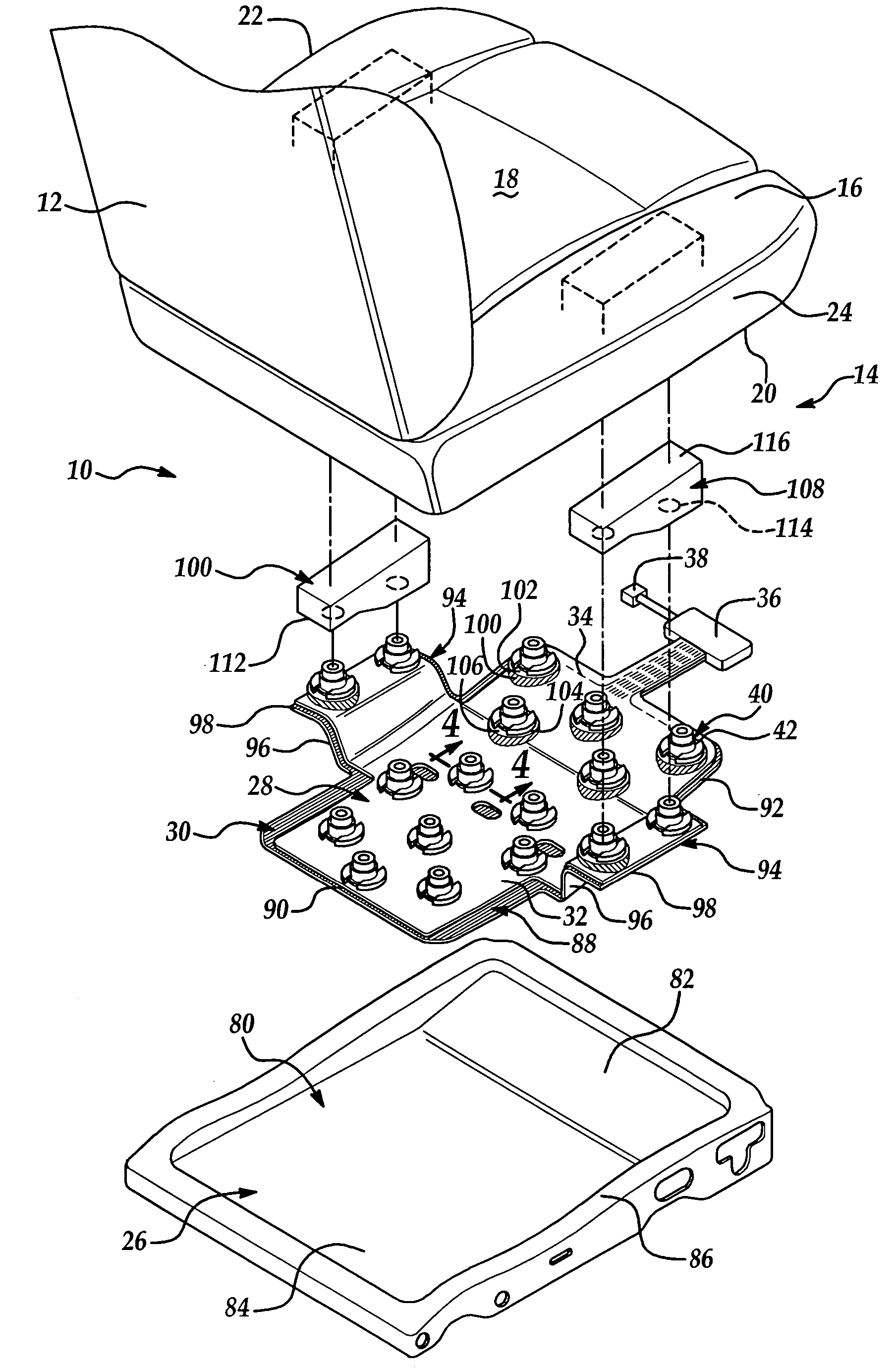
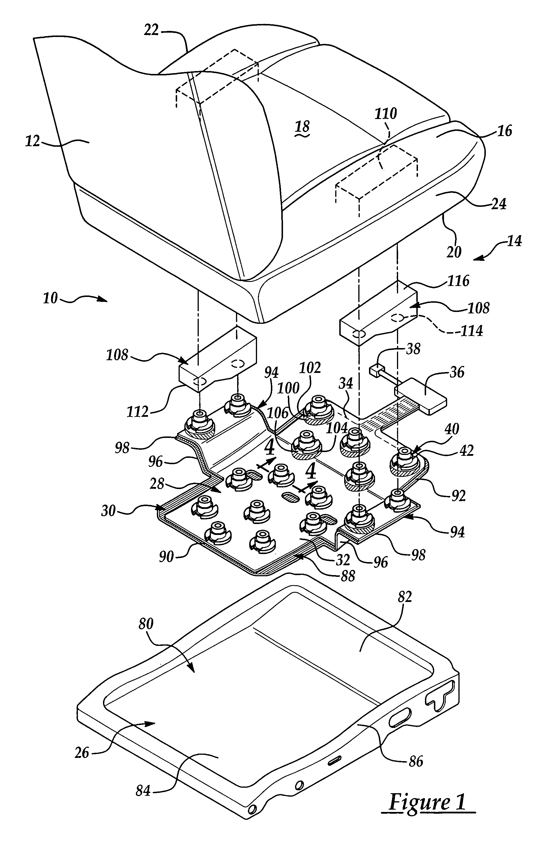
[0025]Referring now to the drawings, where like numerals are used to designate like structure throughout the figures, an exploded view of one embodiment of the vehicle seat assembly of the present invention is generally indicated at 10 in FIG. 1. The vehicle seat assembly 10 includes a seat back, generally indicated at 12, and a lower seat assembly, generally indicated at 14. The lower seat assembly 14 has a seat cushion 16 that defines an upper surface 18, and a lower surface 20 that is spaced from the upper surface 18. The upper surface 18 of the seat cushion 16 may be referred to as the “A-surface” and the lower surface 20 may be referred to as the “B-surface.” The seat cushion 16 also defines an inboard side 22 and an outboard side 24. When an occupant (not shown) is supported on the lower seat assembly 14, the weight of the occupant will apply an axial load directed generally through the upper surface 18 of the seat cushion 16 toward the lower surface 20. Although the weight o...


PUM


Abstract

A vehicle seat assembly that includes a seat cushion having at least one recess disposed thereon. The vehicle seat assembly also has a plurality of sensor assemblies, each including a base and an upper slide member. The upper slide member is supported for movement toward and away from the base in response to a condition of the seat cushion. Additionally, the vehicle seat assembly includes at least one seat cushion insert disposed within the recess of the seat cushion.

Description

CROSS-REFERENCE TO RELATED APPLICATIONS[0001]This application is a continuation-in-part of U.S. Ser. No. 10 / 749,073, entitled “Vehicle Seat Assembly Having a Vehicle Occupant Sensing System and Reinforcing Inserts Positioned Therein,” and filed Dec. 30, 2003, which is a continuation-in-part of U.S. Ser. No. 10 / 606,649, entitled “Encapsulated Spring Sensor Assembly,” and filed Jun. 26, 2003.BACKGROUND OF THE INVENTION[0002]1. Field of the Invention[0003]The present invention relates, generally, to a vehicle seat assembly, and more particularly to a vehicle seat assembly having a vehicle occupant sensing system and a seat cushion insert positioned therein.[0004]2. Description of the Related Art[0005]Automotive vehicles employ seating systems that accommodate the passengers of the vehicle. The seating systems include restraint systems that are calculated to restrain and protect the occupants in the event of a collision. The primary restraint system commonly employed in most vehicles to...

Claims


Application Information

Patent Timeline
Patent Type & Authority Patents(United States)
IPC IPC(8): A47C31/00B60N2/00B60R21/01B60R21/015G01G19/414
CPCB60N2/002B60R21/01516G01G19/4142B60R21/015
Inventor ALI, ASADYOUNG, OLIVER
Owner LEAR CORP
Why Eureka
Try Eureka