Image forming apparatus

a technology of image forming and forming tubes, which is applied in the direction of printing, other printing apparatus, etc., can solve the problems of reducing the efficiency of image forming, large apparatus overall size, and long time taken for maintenance, and achieve uniform clearance and good image quality

Inactive Publication Date: 2007-02-06
FUJIFILM CORP
View PDF5 Cites 10 Cited by
  • Summary
  • Abstract
  • Description
  • Claims
  • Application Information

AI Technical Summary

Benefits of technology

[0009]The present invention is contrived in view of such circumstances, and an object thereof is to provide an image forming apparatus whereby the clearance between the nozzles and the recording paper can be maintained at a uniform value, and good image quality can be obtained.
[0011]According to the present invention, since the recording medium is suctioned in a state where the first opening section is connected to the suction pipe, and the recording medium is conveyed over the platen which moves horizontally in the direction of conveyance, it is possible to prevent occurrence of waves in the recording medium, and hence the clearance between the nozzles and the recording medium is uniform and the flight distance of the ink is maintained at a uniform distance. Thereby, it is possible to improve the accuracy of the landing position of the ink and hence good image quality can be obtained. A platen is used which is provided with suction holes connected to a suction pipe, through which air is sucked out, and the recording medium is suctioned onto the platen by means of these suction holes.
[0012]Preferably, the nozzles are suctioned in a state where the cap member caps the nozzles and the second opening section of the rotating body is connected to the suction pipe. According to this, since the cap member caps and suctions the nozzles in a state where the second opening section of the rotating body is connected to the suction pipe, then it is possible to prevent blockages in the nozzles.
[0015]Preferably, the platen comprises first and second platens independently movable in the conveyance direction of the recording medium. According to this, since the platen is constituted by the first platen and the second platen, that move independently in the conveyance direction of the recording medium, then conveyance of the recording medium is facilitated.
[0018]According to the present invention, since a platen which moves horizontally is provided on a rotating body for performing nozzle recovery, it is possible to carry out nozzle recovery processing while at the same time maintaining a uniform clearance between the nozzles of the recording head and the recording paper, and hence obtaining good image quality.

Problems solved by technology

This nozzle recovery processing is problematic in that, if the recording head is withdrawn until a region outside the image forming region, then the overall size of the apparatus becomes very large, the time taken to perform maintenance becomes long, and the efficiency of image forming declines.
However, in the case of full-surface marginless printing for forming an image on the entire surface of the recording paper, ink falling beyond the sides of the recording paper may land on the platen unit, and hence there is a risk that the rear surface of the subsequently conveyed recording paper may become soiled.
In the image forming apparatus described in Japanese Patent Application Publication No. 2001-80145, however, since the platen is provided on the circumferential face of the rotating body, close contact between the recording paper and the platen cannot be achieved, and waves may arise in the paper, in addition to which, since the surface of the platen supporting the recording paper, which makes contact with the recording paper, is a curved surface, then the distance of flight of the ink ejected from the nozzles of the recording head is not uniform, and hence image quality will decline.

Method used


Image

  • Image forming apparatus
  • Image forming apparatus
  • Image forming apparatus

Examples


Embodiment Construction

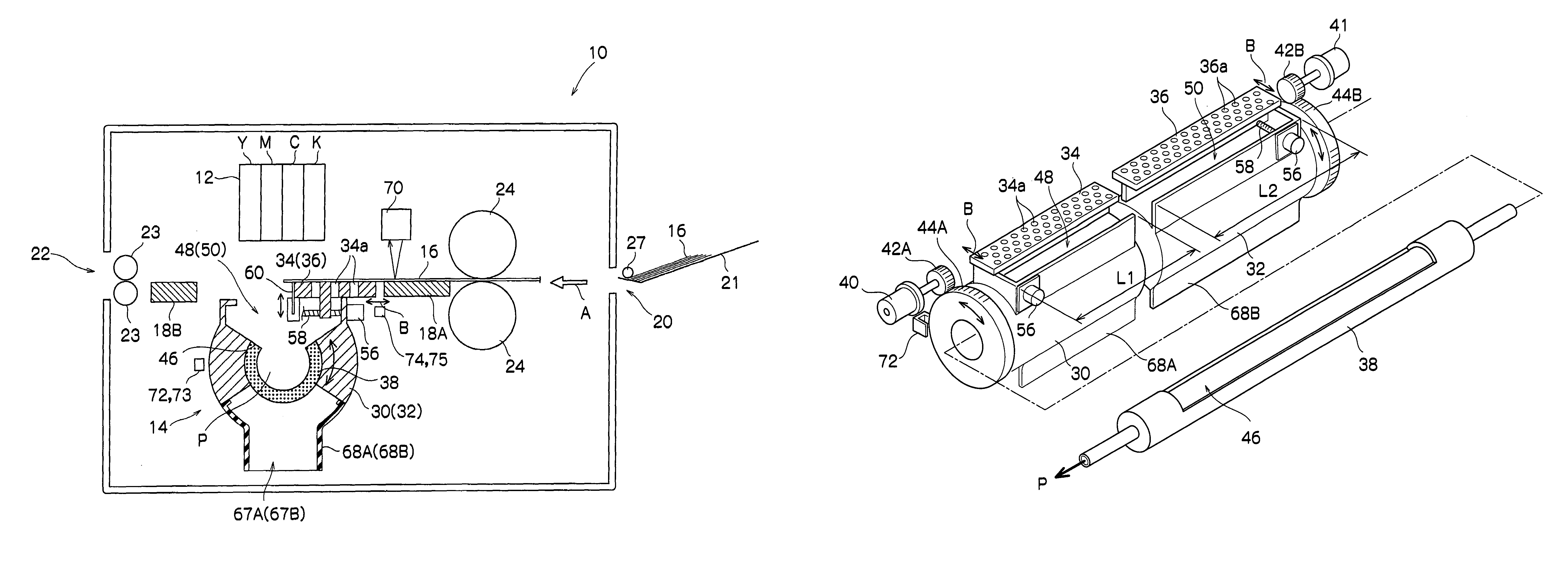
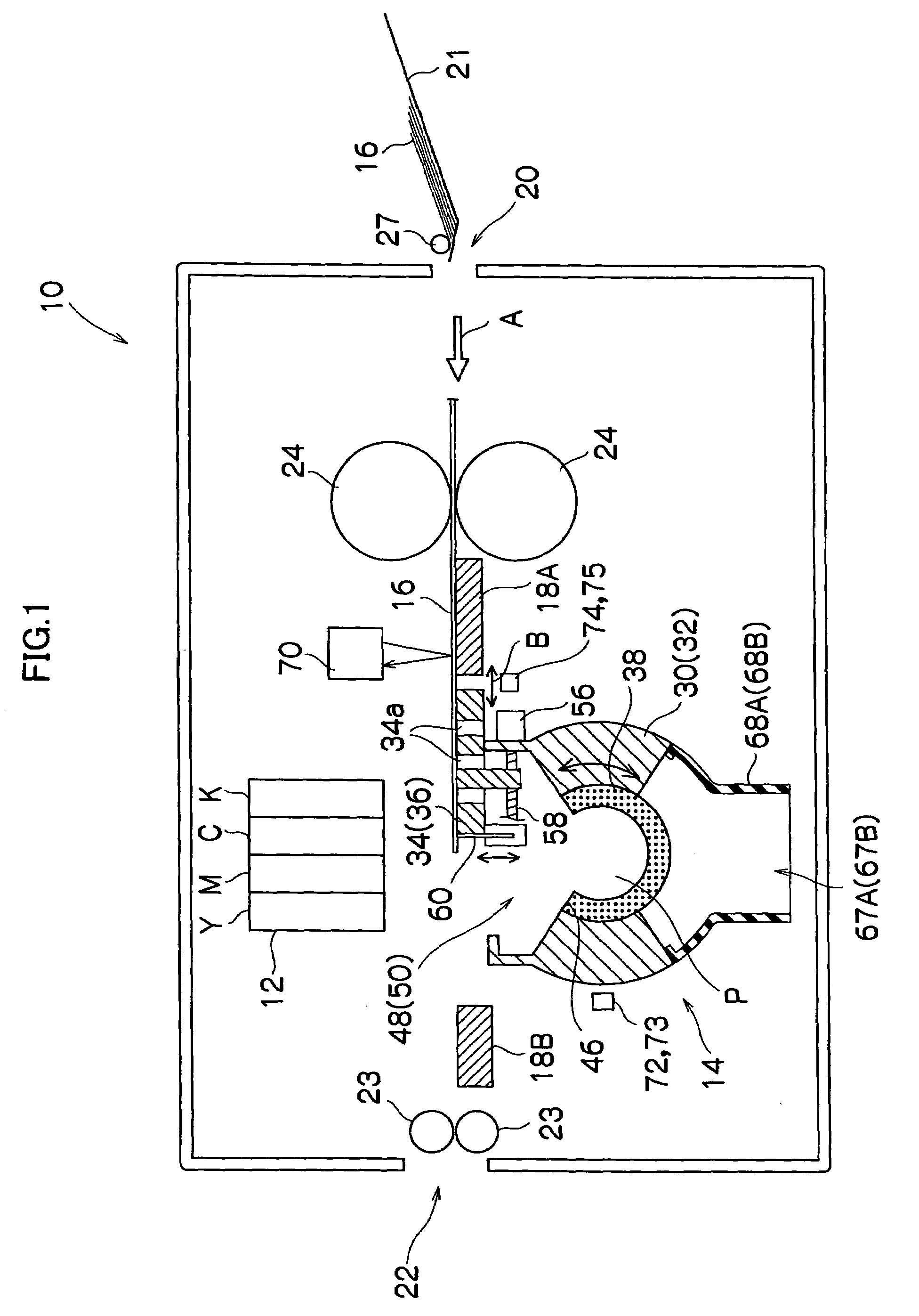
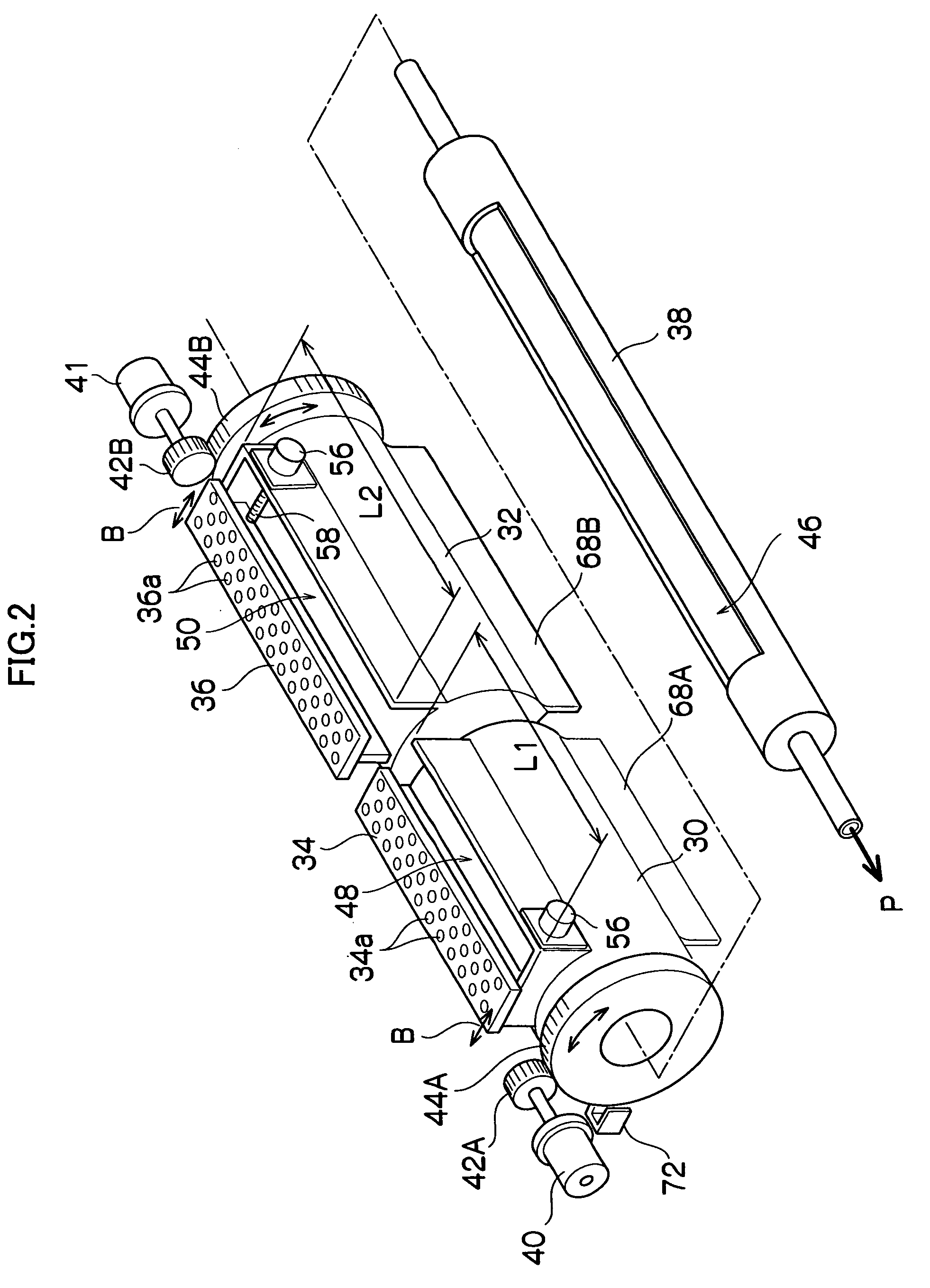
[0028]Below, a first embodiment of an image forming apparatus according to the present invention is described with reference to the accompanying drawings. FIG. 1 is a side view showing the composition of an image forming apparatus 10 according to the first embodiment, and FIG. 2 is an oblique view showing the composition of a nozzle recovery unit 14 used in the image forming apparatus 10.

[0029]The image forming apparatus 10 comprises: a nozzle head 12; a nozzle recovery unit 14 for the recording head 12, disposed in a position opposing the recording head 12; fixed guide plates 18A and 18B for guiding recording paper 16 while holding the recording paper 16 in a flat state; a paper supply unit 20 whereby the recording paper 16 is supplied; and a paper output unit 22 for externally outputting the recording paper 16 on which an image has been formed.

[0030]The recording head 12 is constituted by a so-called line type recording head, wherein a line type head having a length corresponding ...


PUM


Abstract

The image forming apparatus comprises: a line type recording head which is arranged so that a longitudinal direction thereof is substantially orthogonal to a conveyance direction of a recording medium; a suction pipe which is disposed in parallel with the recording head and connected to a suctioning device; a rotating body which is supported rotatably on an outer circumference of the suction pipe and has a first opening section and a second opening section; a platen which is arranged in the first opening section of the rotating body movably in parallel with the conveyance direction of the recording medium; and a cap member which is arranged in the second opening section of the rotating body and adapted to cap nozzles of the recording head, wherein the recording medium is suctioned onto the platen and parallelly moved along a conveyance path in a state where the first opening section of the rotating body is connected to the suction pipe.

Description

[0001]This Nonprovisional application claims priority under 35 U.S.C. § 119(a) on Patent Application No(s). 2003-336237 filed in Japan on Sep. 26, 2003, the entire contents of which are hereby incorporated by reference.BACKGROUND OF THE INVENTION[0002]1. Field of the Invention[0003]The present invention relates to an image forming apparatus and more particularly, to an image forming apparatus provided with a nozzle recovery unit on the side thereof opposing the nozzle surface of a recording head.[0004]2. Description of the Related Art[0005]An image forming apparatus based on an inkjet method forms images on recording paper by discharging ink onto recording paper from a recording head. In an image forming apparatus of this kind, in order to clean the nozzles of the recording head and prevent the nozzles from drying out, nozzle recovery processing is carried out whereby, for example, ink is discharged from the nozzles at prescribed time intervals (preliminary discharge), of the nozzle...

Claims


Application Information

Patent Timeline
Patent Type & Authority Patents(United States)
IPC IPC(8): B41J2/165B41J2/185B41J2/18B41J11/02
CPCB41J2/16585
Inventor TAKATSUKA, TSUTOMUINOUE, HIROSHIKOJIMA, TOSHIYAKACHI, YASUHIKO
Owner FUJIFILM CORP
Why Eureka
Try Eureka