
Rotatable label system and method

a label system and rotating technology, applied in the field of labels, can solve the problems of reducing the size of text and/or graphics, affecting the visual appeal of containers, and insufficient area of prior art labels, and achieve the effect of increasing the indicia surface area

Inactive Publication Date: 2007-02-06
SPINLABEL TECH
View PDF99 Cites 42 Cited by
  • Summary
  • Abstract
  • Description
  • Claims
  • Application Information

AI Technical Summary

Benefits of technology

"The present invention is about a rotatable label system that increases the surface area of indicia. The system includes an inner label with adhesive on the rear surface for attaching it to a container or other object, and an outer label with adhesive on the rear surface for adhering it to the inner label. The outer label is secured about the inner label but can rotate around it. The system also includes a transparent portion in the outer label to allow the indicia on the inner label to be viewed through it. The technical effect of this invention is that it provides a more visable and readable label system that can be rotated for easy viewing and reading of indicia."

Problems solved by technology

Prior art labels may have insufficient area available, however, to accommodate all of the information that a manufacturer may desire to provide to the consumer.
However, reduction of the size of text and / or graphics may adversely affect the visual appeal of the container, or may render some or all of the information illegible to the consumer.
Furthermore, consumers may tend to ignore information presented in “fine print.”
However, the insert is frequently lost or discarded after the initial use of the associated product, thus causing information set forth thereon to become unavailable to the consumer.

Method used


Image

  • Rotatable label system and method
  • Rotatable label system and method
  • Rotatable label system and method

Examples


Embodiment Construction

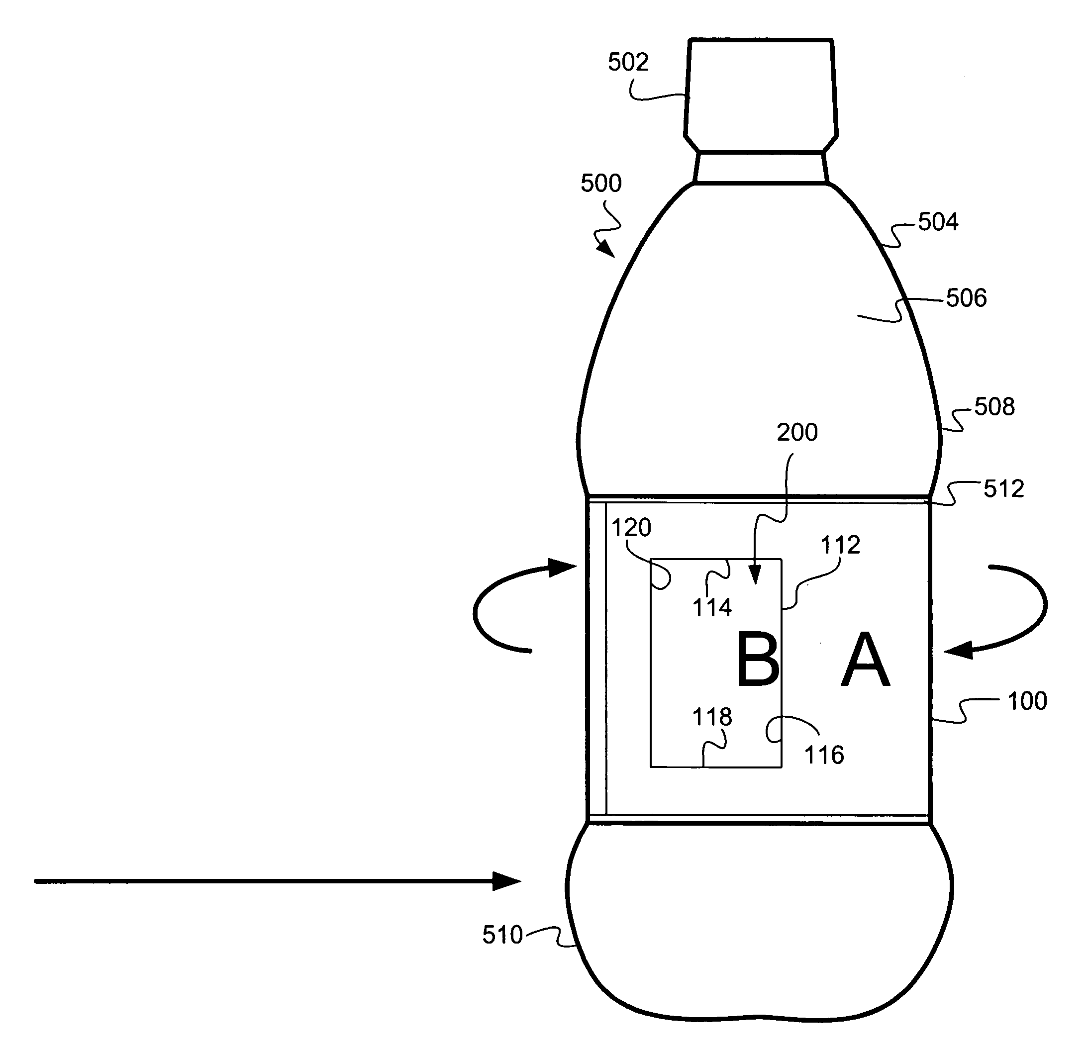
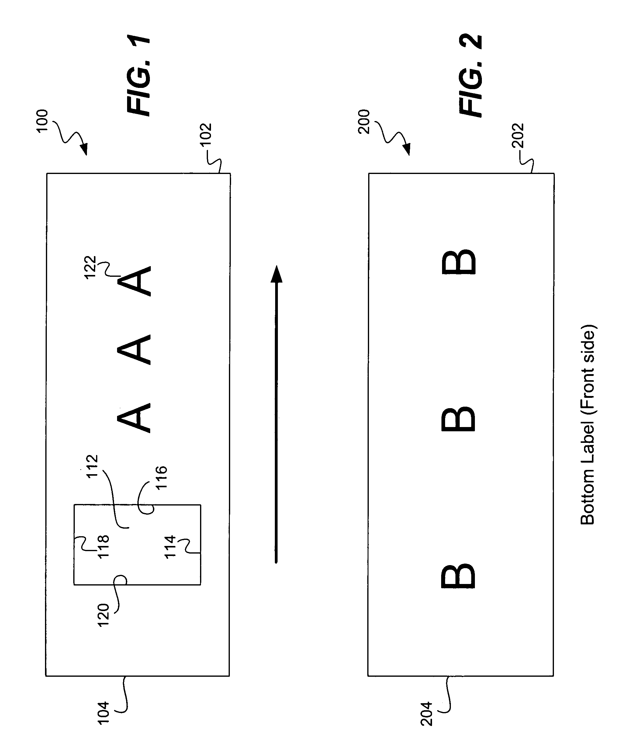
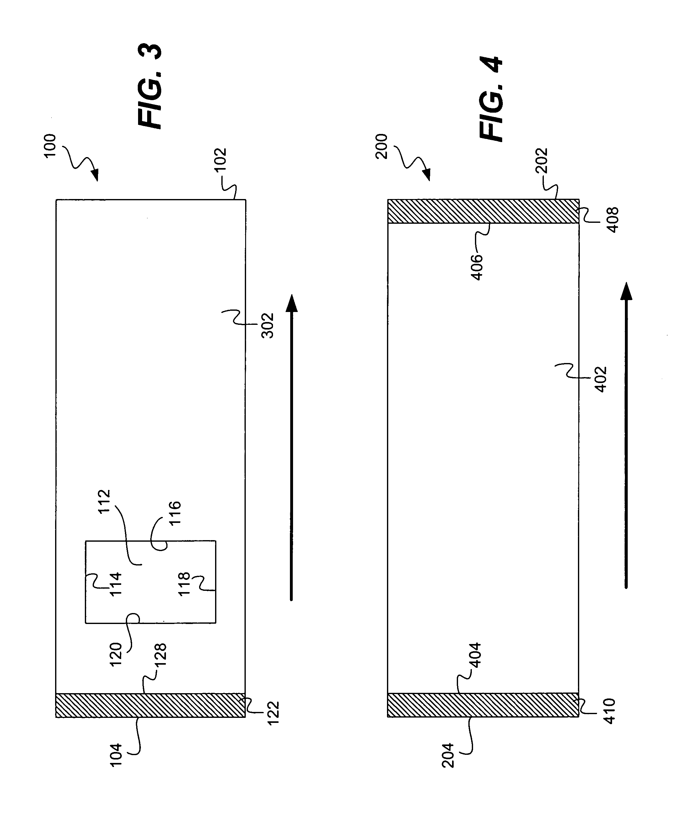
[0044]FIG. 1 illustrates a front surface of an exemplary outer label or shell 100 according to principles of the present invention. As shown, the outer label 100 comprises a leading end 102 and a trailing end 104. The outer label 100 further comprises a transparent portion 112. The transparent portion 112 is illustrated as being defined by edges 114, 116, 118, and 120. The transparent portion 112 may comprise an open window with no material disposed between edges 114–120; or, alternatively, the transparent portion 112 may comprise a transparent film or the like to permit viewing through the transparent portion 112. As discussed in more detail below, the transparent portion 112 permits an exterior of an underlying container or an underlying inner label, to be viewed through the outer label 100. FIG. 1 also shows writing or other indicia 122 that may comprise outer label messages such as trademarks, contents, usage instructions, and so forth.

[0045]In exemplary embodiments, the transpa...


PUM

PropertyMeasurementUnit
viscosityaaaaaaaaaa
softening pointaaaaaaaaaa
thermal viscosityaaaaaaaaaa

Abstract

A system and method are disclosed for constructing a rotatable label and attaching the rotatable label to a container. The rotatable label system comprises an inner label attached to the container and a rotatable outer label. The inner label may have adhesive on a rear surface of a trailing end alone, adhesive on a rear surface of both the leading and trailing end for fixedly attaching it to a container, or adhesive on the entire rear surface. The outer label may only have adhesive on a rear surface at or near a trailing end to secure the outer label to itself. The outer label is temporarily coupled to, the container while the outer label is wrapped around the container. Once the trailing end is attached to a front surface of the outer label at or near a leading end of the outer label, the outer label can be rotated about the container over the inner label. Longitudinal movement of the outer label relative to the container may be restricted by disposing the outer label between top and bottom label panels formed on the container. The outer label is preferably adapted with a transparent portion or window permitting viewing of indicia disposed on the inner label.

Description

CROSS-REFERENCES TO RELATED PATENTS AND APPLICATIONS[0001]The present application is a continuation of and claims the priority benefit U.S. patent application Ser. No. 10 / 112,542 filed Mar. 27, 2002 and entitled “System and Method for a Rotating Sleeve Device” and now abandoned and is also a continuation of and claims the priority benefit of U.S. patent application Ser. No. 10 / 005,428 filed Dec. 3, 2001 now U.S. Pat No. 7,087,298 and entitled “Rotating Label System.”[0002]U.S. patent application Ser. No. 10 / 112,542 is a continuation-in part of U.S. patent application Ser. No. 09 / 866,219 filed May 25, 2001 and now U.S. Pat. No. 6,631,578 issued Oct. 14, 2003 and entitled “Roll Fed Method for Constructing a Rotatable Label System” and a continuation-In-part of U.S. patent application Ser. No. 09 / 551,385 filed Apr. 15, 2000 U.S. Pat. No. 6,402,872 issued Jun. 11, 2002 and entitled “Rotating Label System and Method” and also claims the priority benefit of U.S. Provisional Patent Applica...

Claims


Application Information

Patent Timeline
Patent Type & Authority Patents(United States)
IPC IPC(8): B32B37/10B32B37/30B32B38/10G09F11/02G09F11/23B65C9/20G09F3/02G09F3/04G09F3/10
CPCB65C9/20G09F3/0288G09F3/04G09F3/10Y10T156/1033Y10T156/1142Y10T428/162Y10T428/1476Y10T428/1328Y10S156/921G09F2003/0273
Inventor KEY, STEPHEN M.
Owner SPINLABEL TECH
Learn More